Electronic sensor apparatus

a sensor and electronic technology, applied in the direction of magnetic field measurement using galvano-magnetic devices, magnetic measurements, instruments, etc., can solve the problems of microprocessors that tend to fail or crash frequently, sensor failure to work correctly or accurately, and difficulty in obtaining a quick and clear indication of the value of sensed parameters

Inactive Publication Date: 2001-12-11
GROUP 3 TECH
View PDF7 Cites 12 Cited by
  • Summary
  • Abstract
  • Description
  • Claims
  • Application Information

AI Technical Summary

Benefits of technology

A sensor as discussed throughout this specification may be used to measure a particular parameter or value associated with an object or a region. For example, in some embodiments the sensor may be configured to measure magnetic field strength, electric field strength, temperature, mass, density, or any other number of parameters which can be measured using known types of transducers. The present invention may be employed to simplify and improve the design and operation of sensors that include transducers configured to measure a particular parameter, value or effect.
The present invention provides a number of advantages over existing prior art devices. A single transducer only is required to obtain information with regard to both the measured parameter and also environmental conditions. This eliminates the need to place additional transducers in sensor probes, thereby reducing the cost and complexity of the resulting sensor.

Problems solved by technology

However, a large number of transducers provide output signals that are not directly or linearly proportional to the parameter sensed.
For example, in some instances the transducer output may increase exponentially with a linear increase in the sensed parameter, making it difficult to obtain a quick and clear indication of the sensed parameters value.
Use of a microprocessor in a sensor creates problems if the sensor is to be used in a particularly harsh environment.
For example, if the sensor is to be used in an environment where there is a lot of electrical noise, or where it is possible that high voltages may accidentally be applied to the microprocessor, it is likely that the microprocessor will tend to fail or crash frequently.
This can be a large problem as the sensor will fail to work correctly or accurately if the microprocessor is continually malfunctioning.
In these cases, environmental conditions may change instead of the parameter measured, prompting a change in the transducer's output and hence possibly creating errors in the sensor output.
Provision for these components further complicates the design and manufacture of such sensors.
This approach is relatively costly as a separate transducer and an analog to digital converter is required for each environmental condition monitored and also for the parameter measured.
This can greatly increase the size and complexity of sensing probes used to place the transducers used in a region of interest.
In addition, if the sensors' output is to be sampled at high speed or frequencies, comparatively expensive and fast electrical componentry will also need to be used in the implementation of the sensor.
In existing devices this could only be obtained if an additional digital to analog converter was placed at the output of the sensor.
However this approach again increases the cost of the sensor and further reduces the speed at which the sensors' output can be updated.

Method used


Image

  • Electronic sensor apparatus
  • Electronic sensor apparatus
  • Electronic sensor apparatus

Examples


Embodiment Construction

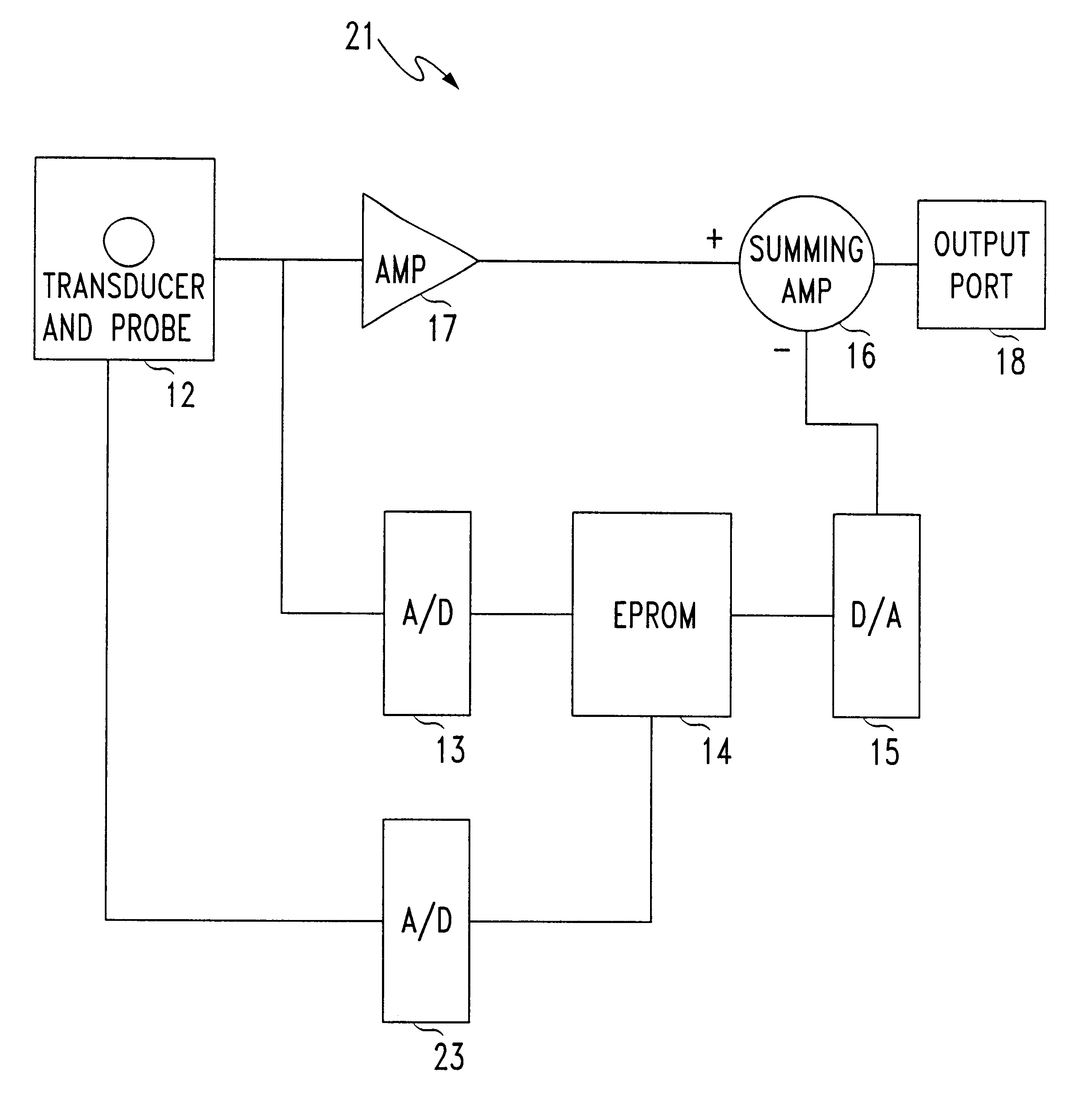
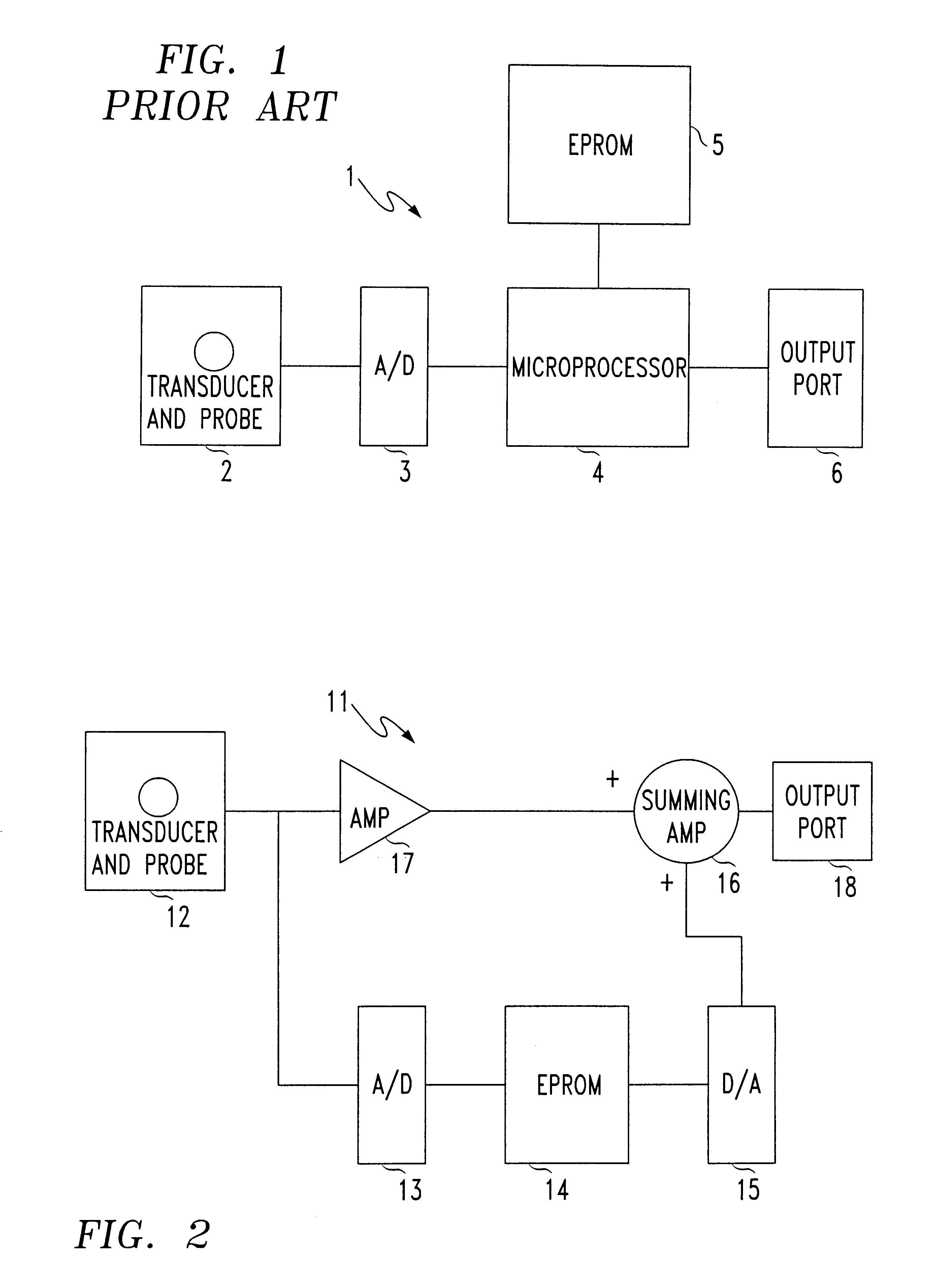
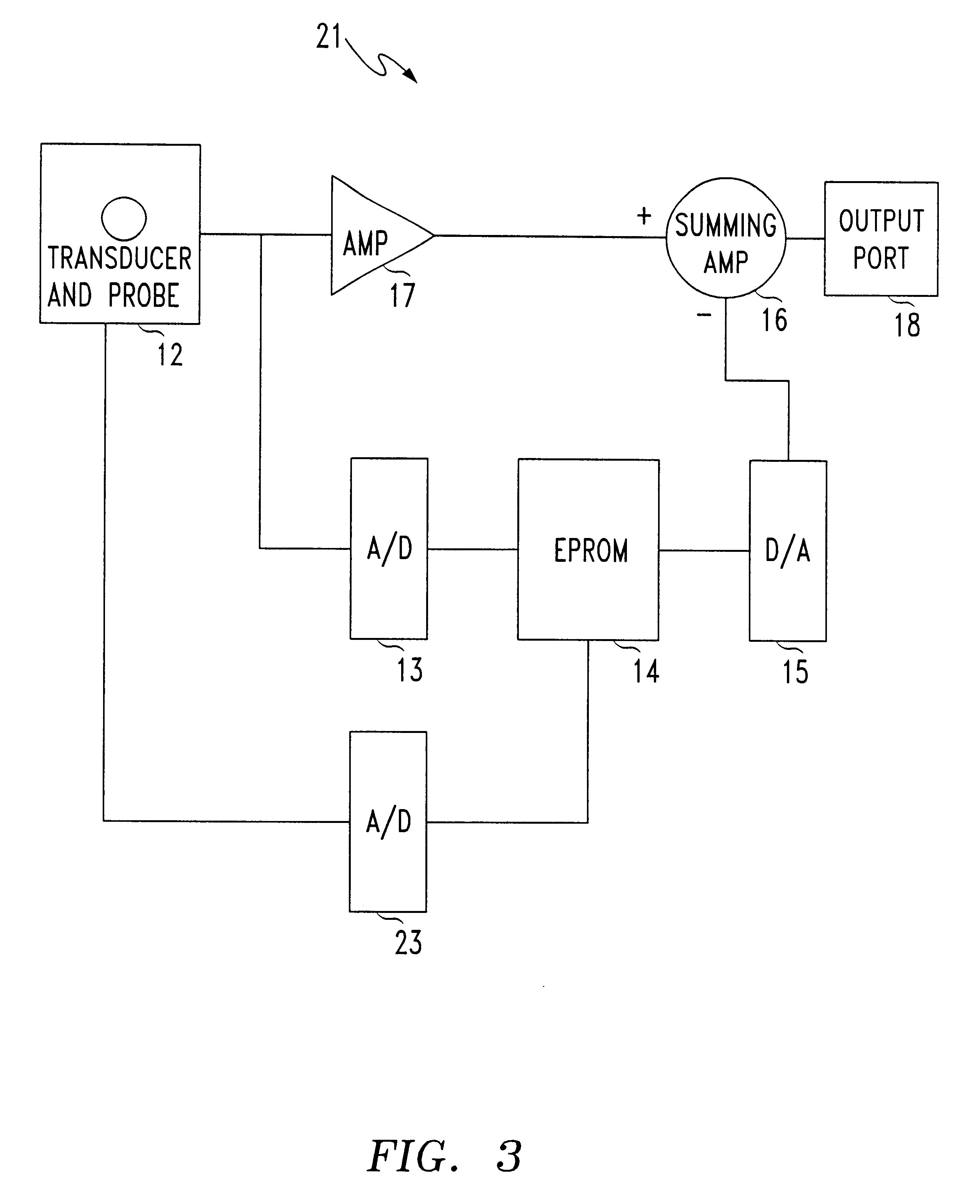
FIG. 1 shows a prior art configuration of a sensor used to measure a parameter. The sensor 1 includes a transducer and probe 2, an analog to digital converter 3, a microprocessor 4, a memory device, shown in this embodiment as an EPROM 5, and an output port 6.

In operation, an analog transducer signal is generated in the transducer 2 and transmitted to the analog to digital converter (ADC) 3. The ADC then converts this analog signal into a digitized signal with a value dependent on the analog signal's voltage, and transmits same to the microprocessor 4.

With the help of information stored in and supplied from the EPROM 5, the microprocessor 4 processes the digitized information supplied to it to provide a digitized output signal to output port 6, where the value represented by this digitized signal will have a substantially linear relationship to that of the parameter measured by the sensor 1.

As discussed previously, the use of a microprocessor 4 in the sensor's construction places so...


PUM


Abstract

A sensor for measuring a parameter includes at least one transducer adapted to provide an analog transducer signal, and at least one converter adapted to convert the analog transducer signal into a digitized transducer signal, and a memory device associated with the converter capable of receiving the digitized transducer signal directly from the converter. The memory device is configured to provide a digitized output value from a memory location, the memory location being associated with or corresponding to the digitized transducer signal received by the memory device.

Description

This invention relates to improvements in sensors that provide or use electrical componentry. Specifically the present invention may be used, and will be described throughout this specification as being used within a magnetic field sensor. However it should be appreciated by those skilled in the art that the present invention has numerous applications outside of magnetic field sensors and reference to the above throughout this specification should in no way be seen as limiting.Numerous modern electrical devices rely on sensors to provide information about an environment. These sensors can be electrically driven and in most cases consist of some form of transducer which provides an output signal which can be measured. The output signal measured will vary depending on the value of the parameter that is sensed by the sensor. As the sensed parameter changes, so will the sensed output of the transducer. However, a large number of transducers provide output signals that are not directly o...

Claims


Application Information

Patent Timeline
IPC IPC(8): G01D3/02G01R33/07G01R33/06G01R15/14G01R15/20
CPCG01D3/022G01R33/07G01R15/202
Inventor MOGININE GUMMER, ROBERT HUGHLAWS, MATTHEW EDWINMCGILL, BRETT GORDON
Owner GROUP 3 TECH
Why Eureka
Try Eureka