
Harmonic measuring method and a current injection device for harmonic measurement

Inactive Publication Date: 2001-12-04
NISSIN ELECTRIC CO LTD +1
View PDF11 Cites 32 Cited by
  • Summary
  • Abstract
  • Description
  • Claims
  • Application Information

AI Technical Summary

Benefits of technology

It is another object of the invention to provide a current injection device used for the harmonic measuring method which is low in the voltage rank, small in size and simple in construction.
It is another object of the invention is to provide a current injection device used for the harmonic measuring method which is small in current capacity and size, with reduction of the time of injecting the currents of the interharmonics.
For this reason, the current injection device 16 may be reduced in size and simplified in construction.
The current injection devices inject the currents sof the interharmonics to the harmonic injection points in a synchronous manner. The interharmonic currents thus injected are added together, and the resultant current, large in level, is fed to a point downstream from the harmonic measuring point. A harmonic characteristic measuring device accurately measures the current and voltage of the interharmonic at the harmonic measuring point, and obtains the value of the admittance of an equivalent circuit of the power line.
Further, the frequency of the output signal of the current injection device is successively varied to the frequencies of the interharmonics, and the current injection is completed for a short time.

Problems solved by technology

Therefore, the obtained equivalent circuit is unsatisfactory in its accuracy.
Thus, the harmonic characteristic in the electric power system that is obtained by the conventional harmonic measuring method is unsatisfactory in its accuracy.
This makes it impossible to select a proper filter for suppressing or removing the harmonic components in or from the electric power system, and hence to effectively suppress or remove the harmonic components.
The current injection device having the high voltage rank and being highly protected against high voltage becomes necessarily large in size, complicated in construction, and high in cost to manufacture.
Therefore, it is impossible to simplify the device construction, to decrease the device cost, and to accurately measure the harmonic characteristic of the upstream bus.
In this case, large current injected is concentrated at one point to cause the problem of a called harmonic interference.
In other words, the harmonic measuring method cannot individually measure the harmonic characteristics of a plural number of power lines branched downstream from the harmonic injection point.
Where the harmonic characteristics of the distribution system, which is of the distribution-line carrier communication type and has the switch control function, are measured by our harmonic measuring method, if the master station and the slave stations are equipped with the current injection devices and the like, an installation cost is increased.
Since our harmonic measuring method requires the harmonic injection device, the measuring device is inevitably increased in size.

Method used


Image

  • Harmonic measuring method and a current injection device for harmonic measurement
  • Harmonic measuring method and a current injection device for harmonic measurement
  • Harmonic measuring method and a current injection device for harmonic measurement

Examples


first embodiment

the present invention will be described with reference to FIG. 1.

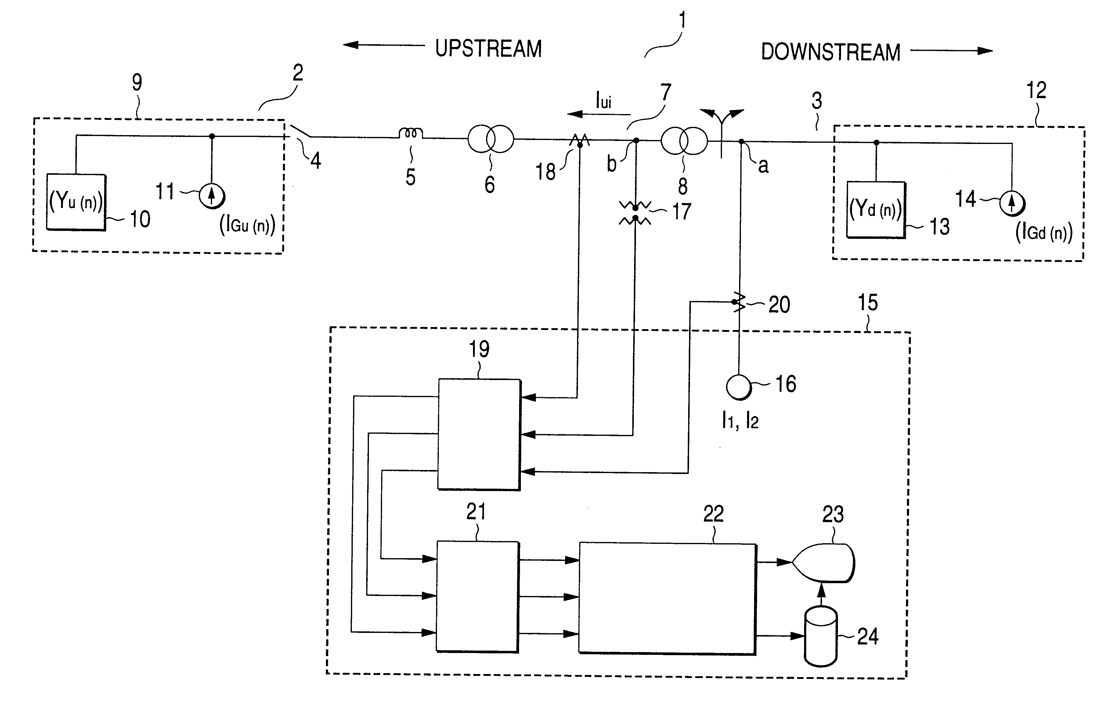
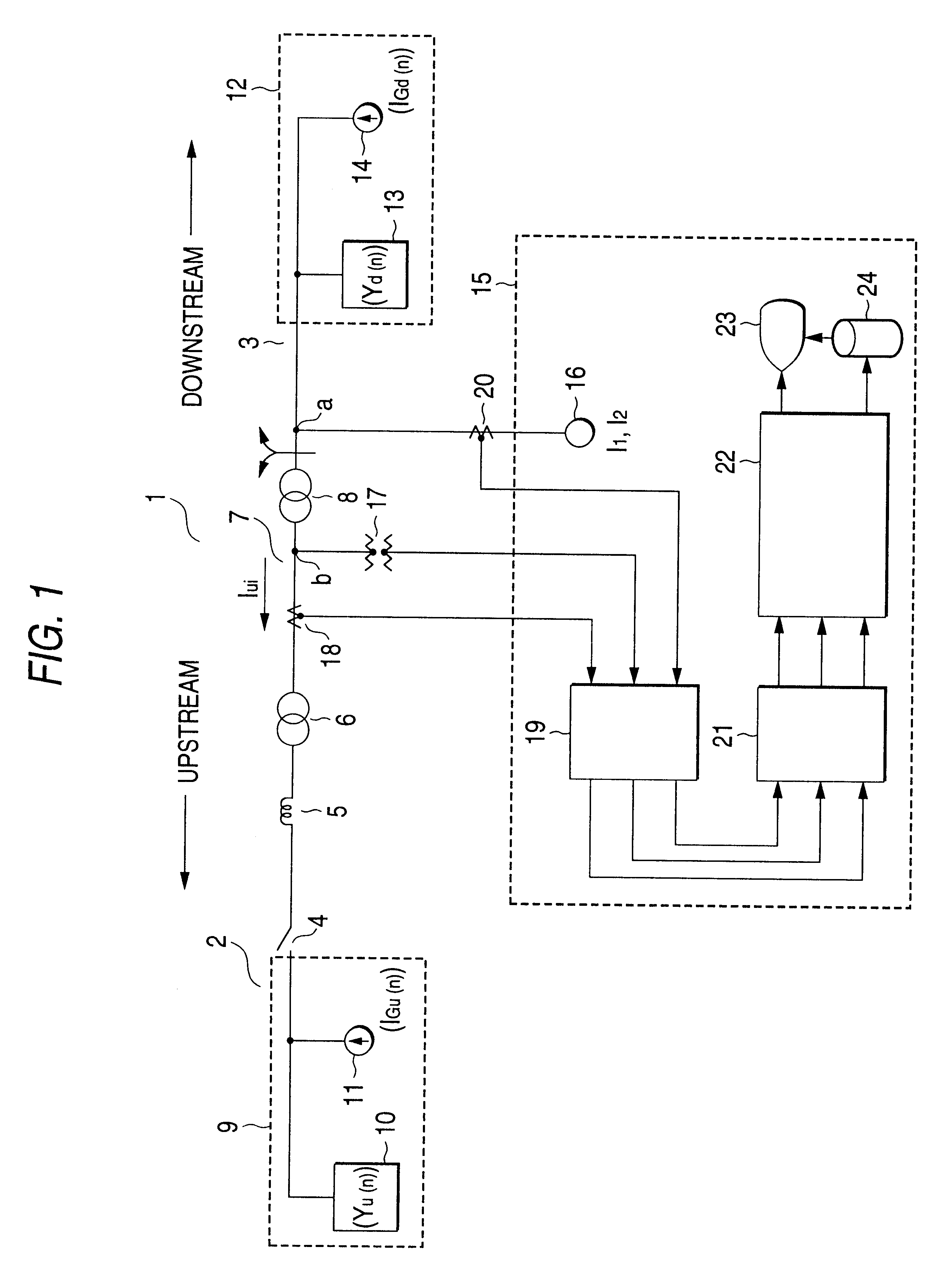
FIG. 1 is a single line system diagram showing how to measure a harmonic characteristic of a 77 kV high voltage bus 2 by a harmonic measuring method which is a first embodiment of the present invention. In the measurement, the currents of interharmonics of specific different frequencies are injected to a position on a 6.6 kV distribution bus 3, which is branched downstream from the 77 kV high voltage bus 2 in an electric power system 1.

The distribution bus 3 is connected to the high voltage bus 2, through a circuit breaker 4, an upstream line impedance 5, a substation (secondary substation) transformer 6, a second high voltage bus 7 at 22 kV and a distribution-substation transformer 8. A harmonic injection point a is set at a point near the secondary side of the distribution-substation transformer 8 of the distribution bus 3, and a harmonic measuring point b is set at a point near the primary side of the distribution-s...

second embodiment

the present invention will be described with reference to FIG. 2.

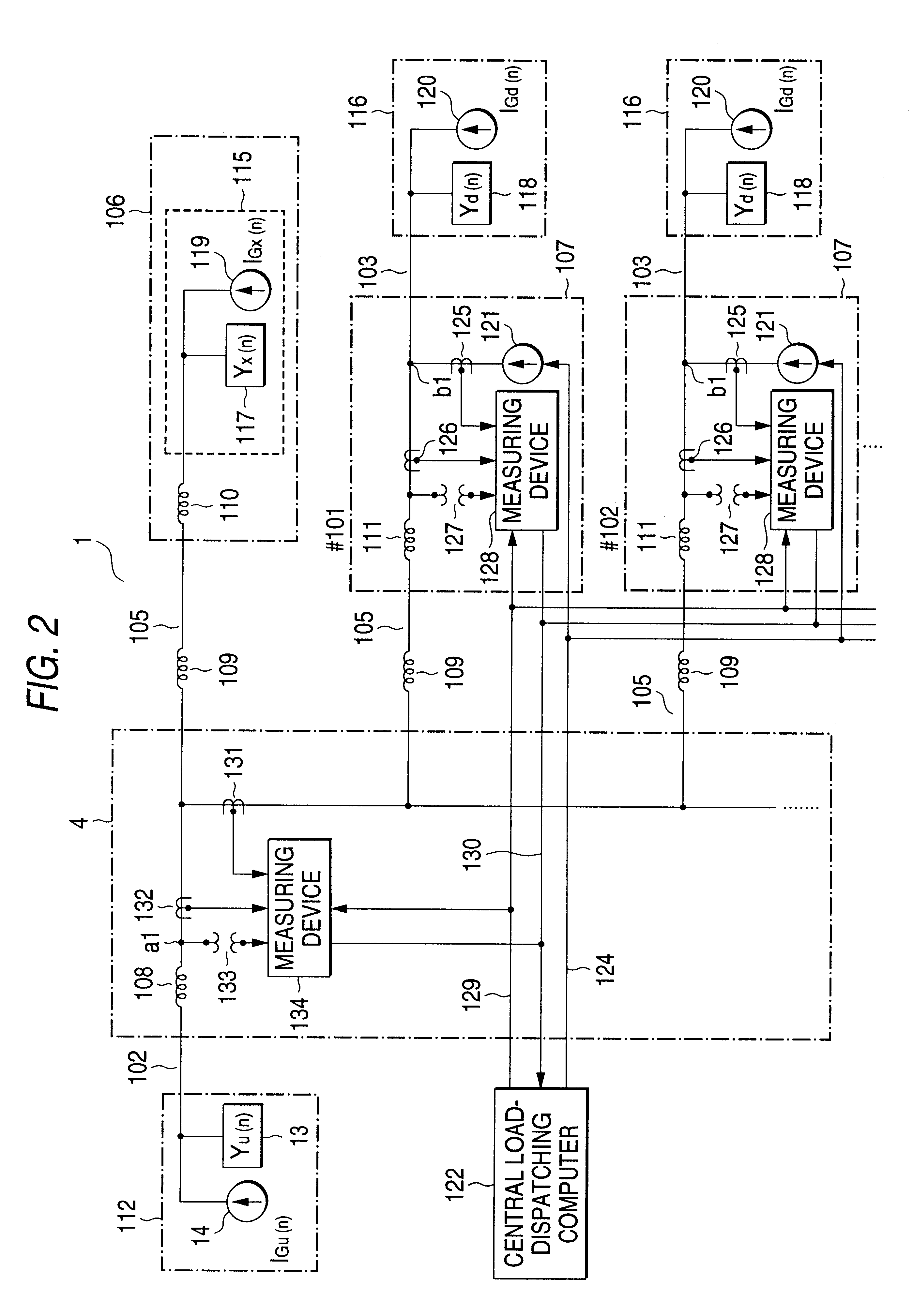
FIG. 2 is a single line system diagram showing how to measure a harmonic characteristic on a 77 kV high voltage bus 102 by a harmonic measuring method presented by the present invention. In the measurement, the currents of interharmonics of specific frequencies are injected to a position on each of 6.6 kV distribution buses 103, which are branched from the 77 kV high voltage bus 102 and located downstream from the latter in an electric power system 1.

A 77 kV electric power on the high voltage bus 102 is transformed into an electric power at 22 kV in voltage. Then, the 22 kV electric power is delivered into 22 kV high voltage buses 105.

Through the 22 kV high voltage buses 105, the high voltage power is distributed to an electric power consumer 106; and a power distribution substation 107 of #101, #102 . . . The substations 107 transform each the received electric power into an electric power at 6.6 kV in voltage and dis...

third embodiment

the present invention will be described with reference to FIG. 3.

FIG. 3 shows an equivalent of an electric power system 201 expressed in the form of a single line system. In the figure, a harmonic injection point a2 is set at a proper position in the electric power system 201. It is preferable that the position is near a position on the power line to which a low-pass filter for harmonics is connected.

Various higher harmonics are present in the electric power system 201. The frequencies of the harmonics are each an integral multiple of the frequency f.sub.s of the fundamental wave of the electric power transmitted by the electric power system 201. The frequency of each higher harmonic is n.times.f.sub.s (n=positive integer). An upstream equivalent circuit 205 of the power line extending upstream from the harmonic injection point a2 is connected to the harmonic injection point a2 while a transformer impedance 202, an upstream power line impedance 203, and a circuit breaker 204 are ins...


PUM


Abstract

A harmonic injection point a is set on a power line extending downstream from a harmonic measuring point b in an electric power system. The currents of interharmonics are injected to the harmonic injection point a by a current injection device. The frequencies of the interharmonics are located on both sides of the frequency of an n-th targeted harmonic in frequency spectrum and each of the frequencies is a nonintegral multiple of the frequency of a fundamental wave of an electric power transmitted by the electric power system. The current values and voltage values of the interharmonics at the harmonic measuring point are detected to thereby obtain admittance values of an equivalent circuit of a power line extending upstream from the harmonic measuring point b when the interharmonics flow therethrough. An admittance value of the equivalent circuit of the power line when the targeted harmonic flows therethrough is determined by interpolating the admittance values for the interharmonics. Measurement is made of a harmonic characteristic of the power line extending upstream from the harmonic measuring point b, which is set at a point located upstream from the harmonic injection point a.

Description

1. Field of the InventionThe present invention relates to a harmonic measuring method in use with an electric power system, and a current injection device used for the harmonic measuring method.2. Description of the Related ArtIn an electric power system, it is very important to reduce the higher harmonics of an electric power.The frequencies of the higher harmonics are each an integral multiple of the frequency f.sub.s of a fundamental wave of the electric power. The frequency of the fifth harmonics typically used, is 5.times.f.sub.s.In an ordinary method for reducing the harmonic components in the electric power, the voltage levels of the harmonics are estimated and a filter for suppressing the harmonics is connected to the power line in the electric power system.To estimate the harmonic voltage levels, a node where a filter is connected to the power line is used as a harmonic measuring point. The harmonic characteristics at points upstream and downstream from the harmonic measuri...

Claims


Application Information

Patent Timeline
IPC IPC(8): G01R23/20G01R19/25
CPCG01R19/2513G01R23/20
Inventor KODA, ISAOTSUKAMOTO, MASAKAZUNISHIMURA, SHOJIUNO, KATSUHIKONATSUDA, YASUYUKIMINOWA, YOSHIFUMI
Owner NISSIN ELECTRIC CO LTD
Learn More