
Circuit and method for generating pixel data elements from analog image data and associated synchronization signals

a pixel data and analog image data technology, applied in the field of graphics systems, can solve the problems of jitter in both reference signals, reference frequency drift over a prolonged period of time, and difficult integration into a relatively small-sized integrated circui

Inactive Publication Date: 2001-11-20
GENESIS MICROCHIP DELAWARE
View PDF41 Cites 38 Cited by
  • Summary
  • Abstract
  • Description
  • Claims
  • Application Information

AI Technical Summary

Problems solved by technology

In addition, the reference frequency can drift over a prolonged period of time due to, for example, temperature changes in the circuits generating the analog source image data.
Further, jitter may be present in both the reference signal and the clock signal generated by the analog PLL.
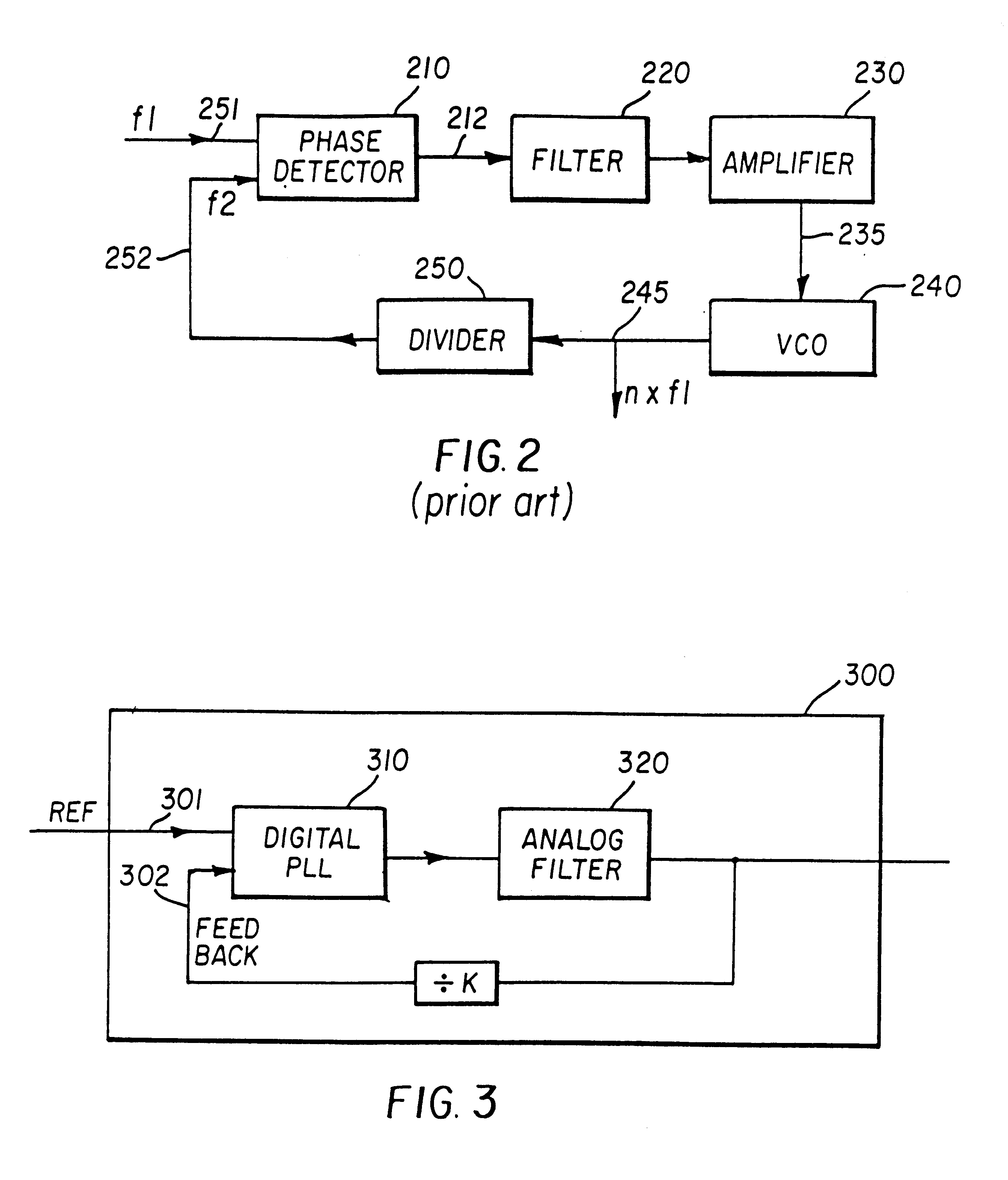
However, such a low bandwidth generally requires a capacitor having a large size, which may be hard to integrate into a relatively small-sized integrated circuits.
One problem with this approach is that noise is introduced into the analog PLL loop due to the external couplings.
Analog PLLs are generally sensitive to such noises, leading to instability in the PLL loop.
Without a low bandwidth in the loop, PLL 200 may be unable to track deviations in the reference signal closely, which may be unacceptable in some situations as explained below.
These deviations are usually more problematic for larger size display screens.
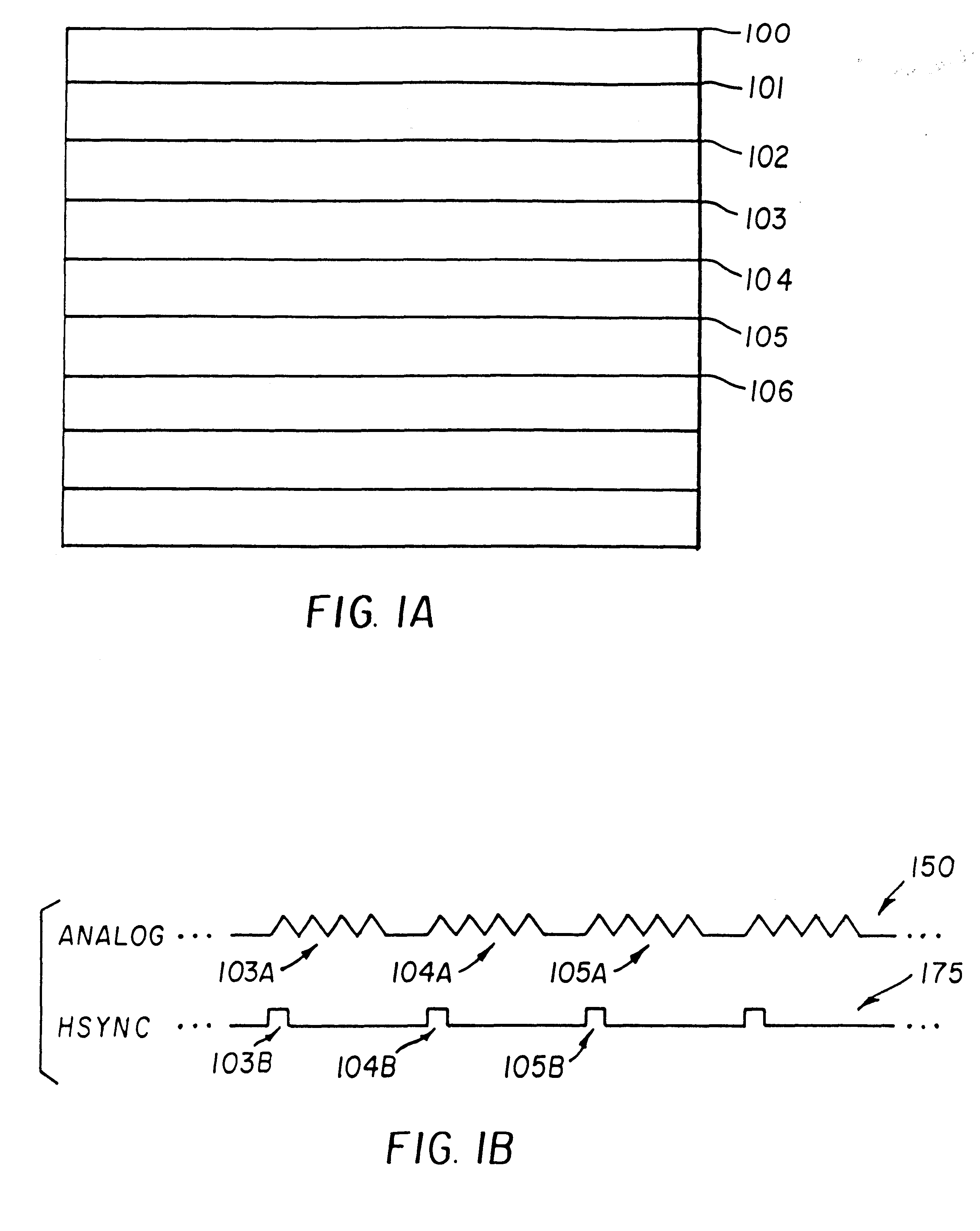
A deviation of 20 nano-seconds may not have a perceptible impact on the display of a 640.times.480 screen due to the relatively larger pixel processing period, whereas the same amount of deviation can cause the display on the large monitor to be skewed by two pixels.
Such a skew between lines is generally perceptible for the human eye and the resulting display quality may be unacceptable.
As already explained in the background section, integration of large capacitors into a semiconductor integrated circuit may be problematic.

Method used


Image

  • Circuit and method for generating pixel data elements from analog image data and associated synchronization signals
  • Circuit and method for generating pixel data elements from analog image data and associated synchronization signals
  • Circuit and method for generating pixel data elements from analog image data and associated synchronization signals

Examples


Embodiment Construction

of Digital Display Unit 770 of the Present Invention

In one embodiment, digital display unit 770 is implemented to operate with a computer system. Digital display unit 770 can be in the form of a flat-panel monitor used in lap-top (note-book computers), a flat-monitor used in desk-top computers and workstations, among other forms. However, it will be apparent to one skilled in the relevant arts how to implement a digital display unit for other graphics system environments such as flat monitor television systems by reading the description provided herein.

FIG. 8 is a block diagram of digital display unit 770 including analog-to-digital converter (ADC) 810, upscaler 820, panel interface 830, clock generator circuit 850, and display screen 100. The output line of ADC 810 is coupled to the input line of upscaler 820. The output line of upscaler 82 is coupled to panel interface 831. The output of panel interface is coupled to display screen 100. Clock generator circuit 850 is coupled to AD...


PUM


Abstract

A clock recovery circuit in a digital display unit for recovering a time reference signal associated with analog display data. The clock recovery circuit includes a phase-locked loop (PLL) implemented in digital domain and an analog filter to eliminate any undesirable frequencies from the output signal of the PLL. The PLL includes independent control loops to track long term frequency drifts of the time reference signal and the transient phase differences respectively. By providing such independent control loops, the generated clock can be better synchronized with the time reference signal.

Description

1. Field of the InventionThe present invention relates to graphics system, and more specifically to a method and apparatus for recovering a clock signal associated with an analog display data received in a digital display unit (e.g., flat-panel monitor) of a graphics system.2. Related ArtDigital display units are often used to display images. A flat-panel monitor generally used in lap-top computers is an example of such a digital display unit. A flat-panel monitor typically receives a source image from a graphics controller circuit and displays the source image. Flat-monitors which are being increasingly deployed with desk-top computers is another example of such a digital display unit. The source image is usually received in the form of analog data such as RGB signals well-known in the art.Digital display devices often need to convert the received analog data into a sequence of pixel data. The need for such a conversion can be appreciated by understanding the general layout of a ty...

Claims


Application Information

Patent Timeline
Patent Type & Authority Patents(United States)
IPC IPC(8): G09G3/20H03L7/085H03L7/08H03L7/07H03L7/093H03L7/06
CPCG09G5/008H03L7/07H03L7/085H03L7/093G06F1/04G09G3/20
Inventor EGLIT, ALEXANDER J.
Owner GENESIS MICROCHIP DELAWARE
Learn More