Laser cutting method and laser cutter

a laser cutter and laser cutting technology, applied in metal-working equipment, welding equipment, manufacturing tools, etc., can solve the problems of difficult to maintain a suitable cutting quality, adversely affect the quality of the cut surface, and insufficient cutting laser energy cannot reach the inside of mild steel

Inactive Publication Date: 2001-11-06
NISSAN TANAKA
View PDF2 Cites 84 Cited by
  • Summary
  • Abstract
  • Description
  • Claims
  • Application Information

AI Technical Summary

Benefits of technology

FIG. 4 shows the effects obtained from the first preferred embodiment of the laser cutting method according to the present invention, and shows the roughness of the cutting surface with respect to the distance from the top surface when mild steel having a thickness of 12 mm is cut.
FIG. 5 shows the effects obtained from the first embodiment of the laser cutting method according to the present invention, and shows the roughness of the cutting surface with respect to the distance from the top surface when mild steel having a thickness of 22 mm is cut.

Problems solved by technology

However, there are many cases in which sufficient cutting laser energy cannot arrive at the inside of the mild steel.
Therefore, it is difficult to maintain a suitable cutting quality when the thickness or the kinds of the material to be cut is changed.
An excess combustion heat is generated due to the small change in conditions when the material is cut, and easily adversely effects to a quality of the cut surface.
Then excess combustion energy adversely effects to the cutting surface and the cutting quality.
Consequently, for example, as shown in FIG. 15, a normal cutting quality can be obtained at the vicinity of the surface 4 of the material to be cut; however, an abnormal cutting quality is often obtained on the inside of the material to be cut.
Therefore, it is impossible to sufficiently improve the cutting quality.
Therefore, it is impossible to solve the problem.

Method used


Image

  • Laser cutting method and laser cutter
  • Laser cutting method and laser cutter
  • Laser cutting method and laser cutter

Examples


first embodiment

the laser cutting method will be explained below.

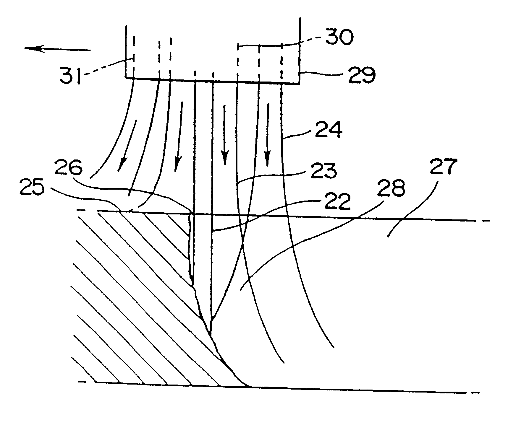
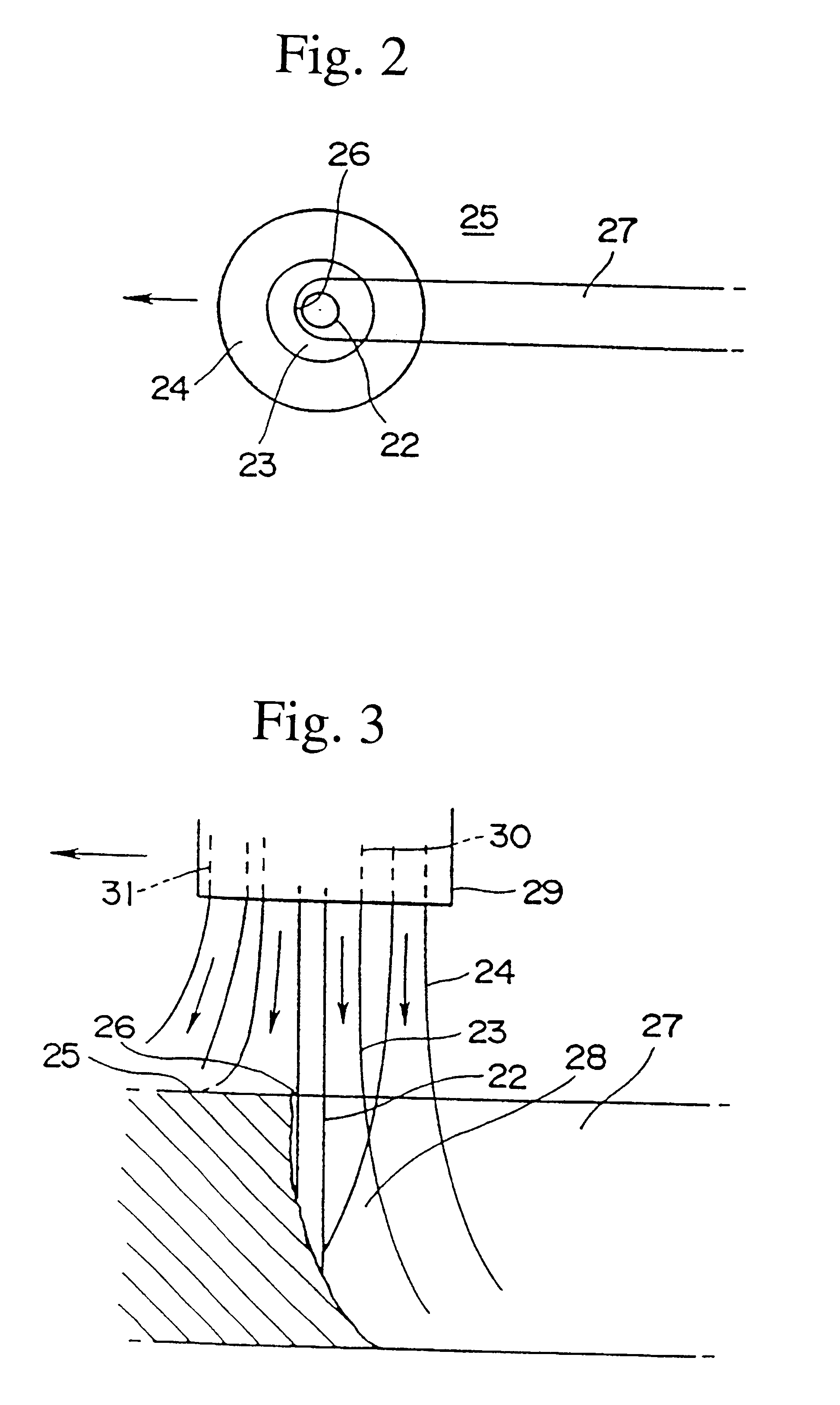
FIG. 2 is a planar view showing the co-axial double nozzle, for example, shown in FIG. 6. In FIG. 2, reference numeral 22 denotes a laser beam, reference numeral 23 denotes a gas containing oxygen at a high concentration (a concentration of 99.5% or more), reference numeral 24 denotes a gas containing oxygen at a low concentration, and reference numeral 25 denotes a material to be cut (steel plate).

The diameter of the laser beam 22 is in a range from 0.1 to 0.5 mm. The gas steam of the high concentration oxygen 23 diffuses at the area within approximately 1.5 mm of the laser beam 22. Furthermore, the gas stream of a mixed gas 24 diffuses to the area surrounding the gas stream of the high concentration oxygen 23. The mixed gas 24 comprises oxygen and the gas other than oxygen such as nitrogen. The oxygen concentration of the mixed gas 24 is lower than that of the high concentration oxygen 23.

The high concentration oxygen 23 and the mix...


PUM

PropertyMeasurementUnit
diameteraaaaaaaaaa
thicknessaaaaaaaaaa
thicknessaaaaaaaaaa

Abstract

A development of a laser cutting method and a laser cutter in which the adverse effects such as self burning to the cutting surface can be prevented, when the material is cut at a high speed, has been desired. In order to achieve the object, the present invention provides a laser cutting method and a laser cutter in which a cutting laser beam 22 is applied to a material 25 to be cut at a cutting point 26, while ejecting gases 23 and 24 to the cutting point 26 or its surrounding area from a plurality of nozzle openings 30 and 31 arranged in a ring or in a line, wherein the oxygen concentrations of the gases 23 and 24 ejecting from at least one of the nozzle opening 30 and 31 are changed to adjust the oxygen concentration distribution in an area within several millimeters of the cutting point 26; thereby the cutting quality can be improved.

Description

The present invention relates to a laser cutting method and a laser cutter.When mild steel is cut with a laser having a small power relative to the thickness of the mild steel, sufficient cutting laser energy can be obtained at the vicinity of the surface of the mild steel at which the laser is applied. However, there are many cases in which sufficient cutting laser energy cannot arrive at the inside of the mild steel. Therefore, in recent years, high concentration (purity) oxygen (having a concentration (purity) of 99.5% or more) is supplied to the vicinity of the cutting point by use a co-axial double nozzle 1a and 1b as shown in FIGS. 10 and 11, a co-axial triple nozzle (not shown in Figures), or an auxiliary nozzle 2 as shown in FIG. 12. Thereby, a sufficient oxygen concentration for cutting the inside of the mild steel is maintained. Heat is generated due to the oxidation reaction between steel and the supplied oxygen, and the heat compensates for the deficiency of laser energy...

Claims


Application Information

Patent Timeline
Patent Type & Authority Patents(United States)
IPC IPC(8): B23K26/14B23K26/12B23K26/064
CPCB23K26/12B23K26/123B23K26/125B23K26/14B23K26/1447B23K26/1476B23K26/1437B23K26/142B23K26/16
Inventor NAGATA, YOZONAGAHORI, MASAYUKI
Owner NISSAN TANAKA
Why Eureka
Try Eureka