
Trunk line exchange system

a technology of trunk line and exchange system, which is applied in the direction of electrical equipment, interconnection arrangements, supervisory/monitoring/testing arrangements, etc., can solve the problems of reducing the average employment efficiency of trunk lines in the trunk line exchange system, and achieve the effect of avoiding the fall of an exchange apparatus in any region and efficient utilization of transmission resources

Inactive Publication Date: 2001-10-09
NEC CORP
View PDF7 Cites 0 Cited by
  • Summary
  • Abstract
  • Description
  • Claims
  • Application Information

AI Technical Summary

Benefits of technology

to provide a system capable of enabling the efficient utilization of the transmission resource and capable also of avoiding an exchange apparatus at any region from falling into congestion.
According to the present invention, line switch means are disposed at a front position of a trunk line exchange apparatus facing toward the other trunk line exchange apparatus, and by controlling opening and closing of the line switch means, the number of lines for each region can be re-distributed in response to the traffic of each region and the system can be preferably prevented from falling into congestion.

Problems solved by technology

In the above described conventional trunk line exchange system, there are some drawbacks, in addition to the costly spare lines for preventing deterioration of call connections in a congested condition, in that, as shown in FIG. 4, even if an activity ratio of a trunk line for a busy region is nearly 100%, lines in another region are inactive due to the time difference, which results in reducing the average employment efficiency of trunk lines in the whole trunk line exchange system, which may be designated a transmission resource.

Method used


Image

  • Trunk line exchange system
  • Trunk line exchange system
  • Trunk line exchange system

Examples


first embodiment

A. First Embodiment

(1) Construction

FIG. 1 is a block diagram showing a schematic construction of the trunk line exchange apparatus system according to the first embodiment of the present invention. As shown in the figure, a trunk line exchange system of the present invention comprises:

region traffic managing systems 11 and 21 for executing re-distribution of transmission lines for each region for an effective utilization of the system resource;

trunk line exchange apparatuses 12, 22, and 32 located at respective regions for conducting international trunk line exchange;

interface units 13, 23, 33, 112, and 212 connected with both said trunk line exchange apparatuses 12, 22, 32 and said region traffic managing system 11 and 21, for exchanging control signals relating to information as to line activity ratios, line closing, and line switching etc.;

a plurality of transmission lines 14, 24 and 34 for connecting between the trunk line exchange apparatuses 12, 22, and 32 and the region traff...

second embodiment

B. The Second Embodiment

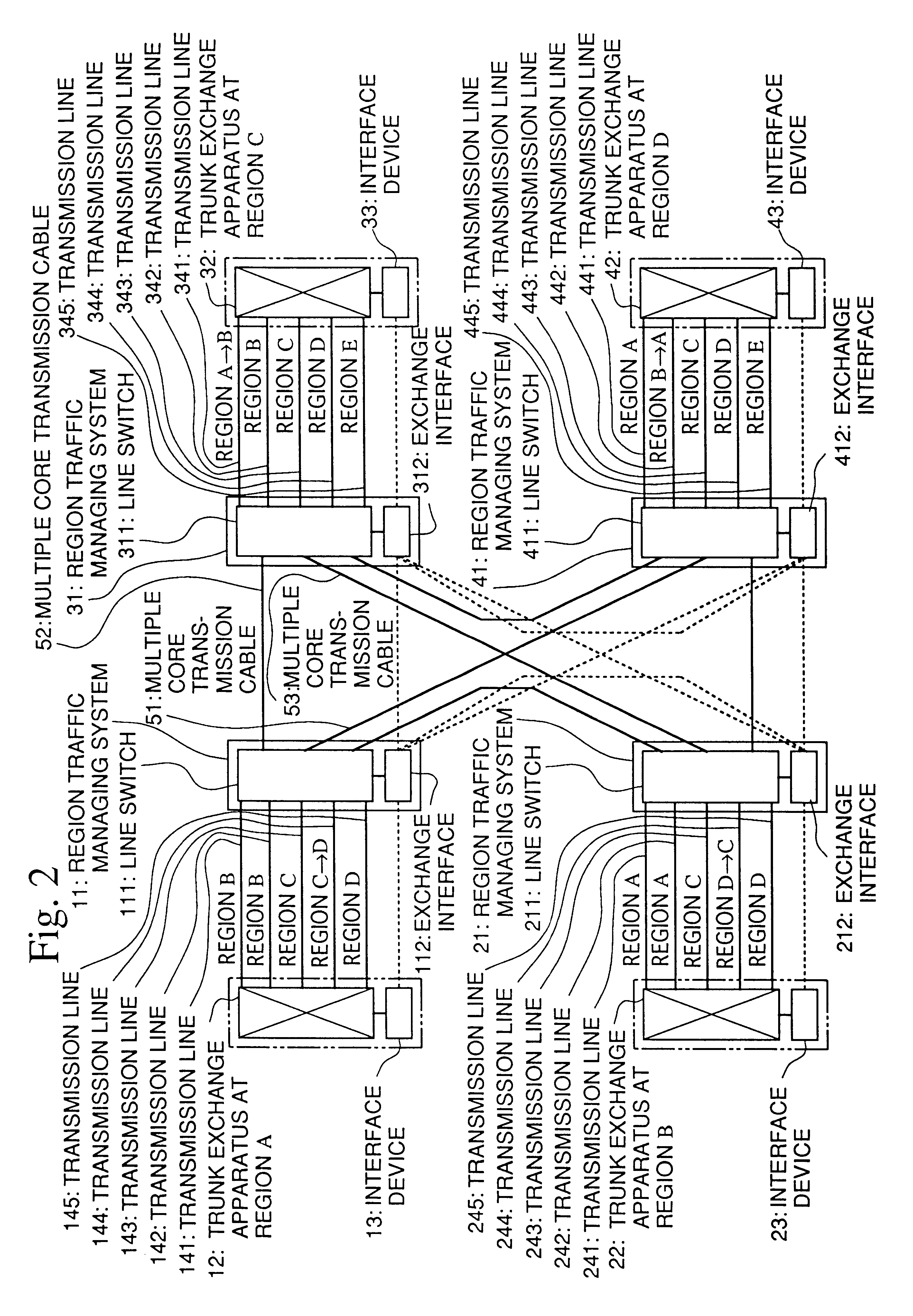
In the above first embodiment, re-distribution is conducted for some of the transmission lines connecting each region and the multiple core transmission cable. In contrast, in the second embodiment, as shown in FIG. 2, a network is formed for managing the region traffic so as to enable execution of the re-distribution of transmission lines between different regions connected by a plurality of multiple core transmission cables 52 to 54. In this case, it is more preferable and more effective to form such networks than in the first embodiment, since the longer the distance between respective regions apart, the larger the time differences between respective regions.

(1) Construction

FIG. 2 is a block diagram showing a schematic construction of the trunk line exchange system according to the second embodiment of the present invention. As shown in this figure, the trunk line exchange system of the second embodiment comprises:

region traffic managing systems 11, 21, 31...


PUM


Abstract

The present trunk line exchange system is capable of coping with the busy hour calls without falling into congestion by executing re-distribution of the number of communication lines to the busy region from the quite region, which results in yielding efficient utilization of the communication lines. The system is also capable of avoiding the congestion of the exchange system, since it is not necessary to conduct a series of operations such as recalls / alternative line processing.

Description

1. Field of the InventionThis invention relates to a trunk line exchange system in an international communication network, and particularly relates to a trunk line exchange system capable of executing re-distribution of the number of international transmission lines for respective regions in the international communication network.This application is based on Patent Application No. Hei 9-221610 filed in Japan, the content of which is incorporated herein by reference.2. Background ArtConventionally, in the international network which conducts the international exchange of the trunk lines, a fixed number of transmission lines are distributed so as to meet demand in each country (which is called a "region", hereinafter). The number of transmission lines for a region is determined by calculating a ratio of average traffic to busy hour traffic for each region and a fixed number of communication lines are normally allocated for each region. Moreover, the number of transmission lines for e...

Claims


Application Information

Patent Timeline
IPC IPC(8): H04Q3/00H04M3/00H04M3/22H04Q3/545H04Q3/64
CPCH04Q3/0091H04Q2213/13148H04Q2213/13164H04Q2213/13166H04Q2213/13349H04Q2213/1338
Inventor KUMAKURA, HIROSHI
Owner NEC CORP
Learn More