
Methods and apparatus for treating fibrillation and creating defibrillation waveforms

Inactive Publication Date: 2001-10-02
INTERMEDICS
View PDF23 Cites 28 Cited by
  • Summary
  • Abstract
  • Description
  • Claims
  • Application Information

AI Technical Summary

Problems solved by technology

However, people suffering from disease may experience abnormal arrhythmias that may require special, and in some instances immediate, treatment.
Fibrillation is a tachyarrhythmia characterized by the commencement of completely uncoordinated random contractions by sections of conductive cardiac tissue of the affected chamber, quickly resulting in a complete loss of synchronous contraction of the overall mass of tissue and a consequent loss of the blood-pumping capability of that chamber.
For a variety of reasons, a person's heart may not function properly and, thus, endanger the person's well-being.
These pacemakers did not monitor the condition of the heart.
However, it was found that pacemakers of this type used an inordinate amount of energy due to the constant pulse production.
Accordingly, if a heart, even for a short period, is able to beat on its own, providing an electrical stimulation pulse using a pacemaker wastes the pacemaker's energy.
Indeed, the complexity of pacemakers has continued to increase in order to address the physiological needs of patients as well as the efficiency, longevity, and reliability of the pacemaker.
Unfortunately, the heart of a person in need of a pacemaker may not be able to beat faster on its own.
This property renders the AV junctional tissue unable to respond fully to the more rapid atrial contractions.
Such circumstances may include, for example, instances where the patient suffers from ventricular heart disease and cannot easily withstand even the small consequent reduction of ventricular pumping capability, as well as instances where the rapid atrial rhythm is responsible for an excessively rapid ventricular rate.
However, in contrast to atrial fibrillation, ventricular fibrillation manifests an instantaneous cessation of cardiac output as the result of the ineffectual quivering of the ventricles - a condition that typically requires almost immediate treatment.
While such a waveform typically overcomes the fibrillation of the heart, if it is not of sufficient intensity refibrillation may occur.
While biphasic waveforms appear to exhibit greater efficacy than monophasic waveforms, various problems still exist.
While a variety of biphasic waveforms have been considered for defibrillation, no known waveform appears to be best suited for every situation.
Furthermore, many waveforms remain theoretical, because no circuit suitable for use in an implantable ICD has been designed to create the waveform.

Method used


Image

  • Methods and apparatus for treating fibrillation and creating defibrillation waveforms
  • Methods and apparatus for treating fibrillation and creating defibrillation waveforms
  • Methods and apparatus for treating fibrillation and creating defibrillation waveforms

Examples


Embodiment Construction

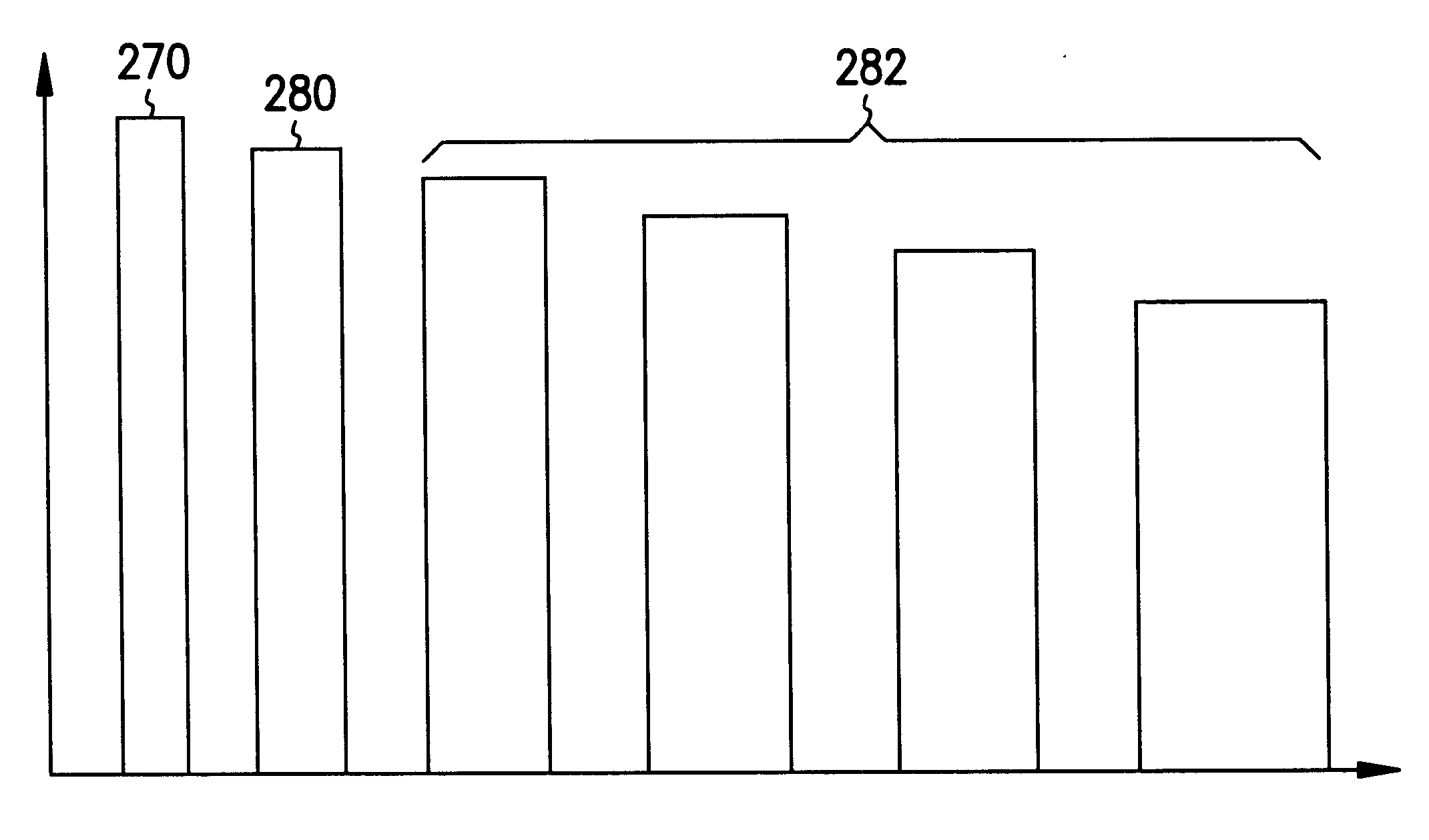
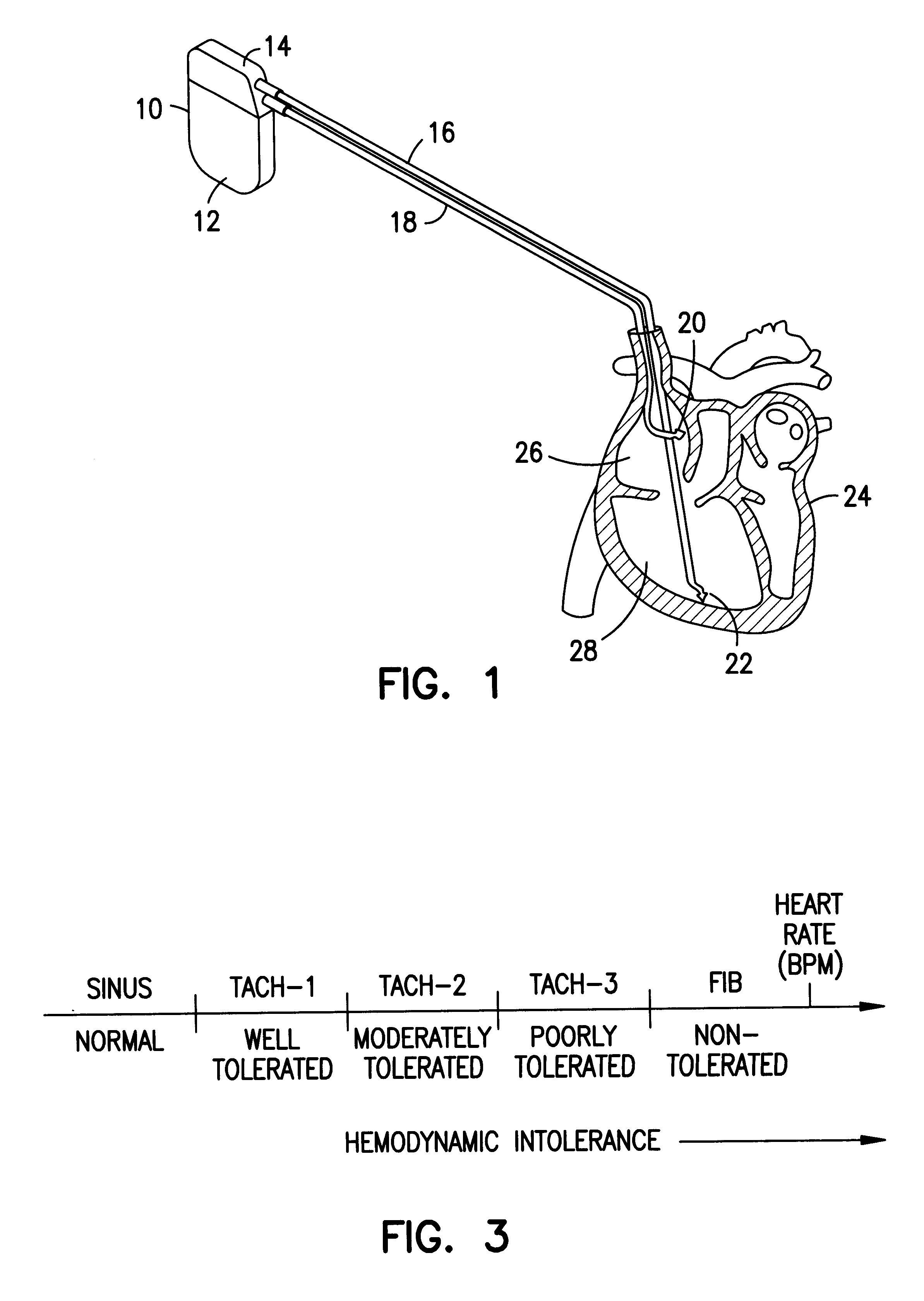
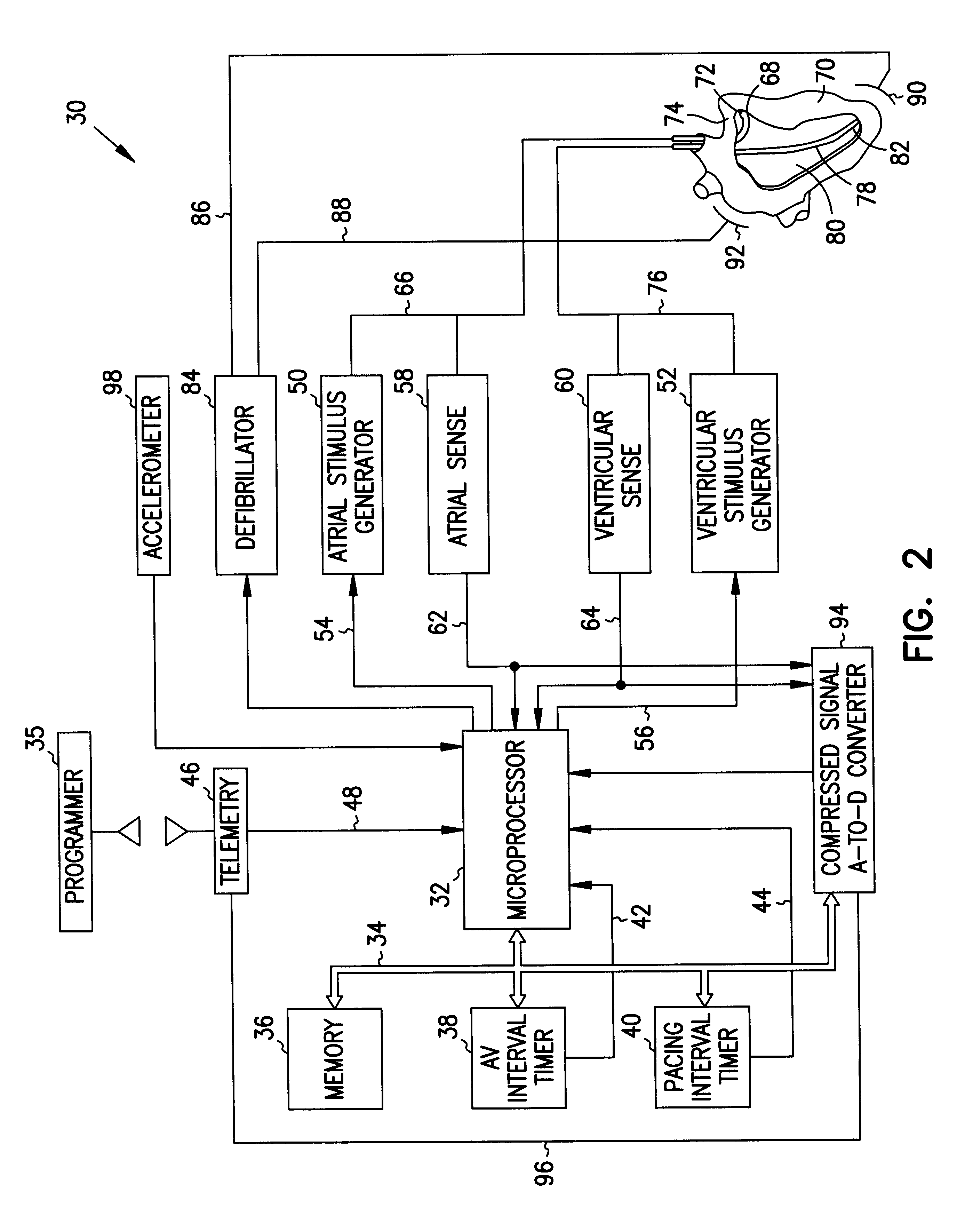
Turning now to the drawings, and referring initially to FIG. 1, one embodiment of a dual-chamber cardiac stimulator is illustrated and generally designated by the reference numeral 10. As discussed below, the cardiac stimulator 10 advantageously includes a defibrillator circuit that produces one or more waveforms for treating a detected fibrillation. The general structure and operation of the cardiac stimulator 10 will be discussed with reference to FIGS. 1-3. Then, various waveforms for treating fibrillation will be discussed with reference to FIGS. 4-32. Once these waveforms have been described, various exemplary methods and circuits for creating these waveforms will be described with reference to FIGS. 33-37.

As shown in FIG. 1, the body of the cardiac stimulator 10 includes a case 12 and a header 14. The cardiac stimulator 10 may be implantable or non-implantable. If implantable, the case 12 and the header 14 are hermetically sealed to prevent bodily fluids from damaging the inte...


PUM


Abstract

Methods and apparatus for treating fibrillation utilize biphasic waveforms. A cardiac stimulator includes a defibrillation circuit that uses a pulse width modulated capacitive discharge to generate various biphasic waveforms, one or more of which may be delivered to the heart to treat the fibrillation.

Description

1. Field of the InventionThe present invention relates generally to cardiac stimulators and, more particularly, to cardiac stimulators having the ability to treat fibrillations.2. Description of the Related ArtThis section is intended to introduce the reader to various aspects of art which may be related to various aspects of the present invention which are described and / or claimed below. This discussion is believed to be helpful in providing the reader with background information to facilitate a better understanding of the various aspects of the present invention. Accordingly, it should be understood that these statements are to be read in this light, and not as admissions of prior art.As most people are aware, the human heart is an organ having four chambers. A septum divides the heart in half, with each half having two chambers. The upper chambers are referred to as the left and right atria, and the lower chambers are referred to as the left and right ventricles. Deoxygenated blo...

Claims


Application Information

Patent Timeline
IPC IPC(8): A61N1/39
CPCA61N1/3906A61N1/3956
Inventor RUBIN, LEOBONNERUP, CHRISTOPHER A.SCHROEPPEL, EDWARD A.
Owner INTERMEDICS
Learn More