
Fuel injection control

a technology for controlling the fuel injection of the engine, which is applied in the direction of electric control, fuel injection control, machines/engines, etc., can solve the problems of increasing the volume of the engine, increasing the cost of the engine to manufacture, and the fact that the internal combustion engine does not reliably produce air-fuel charges

Inactive Publication Date: 2001-09-11
SANSHIN KOGYO CO LTD
View PDF6 Cites 38 Cited by
  • Summary
  • Abstract
  • Description
  • Claims
  • Application Information

AI Technical Summary

Benefits of technology

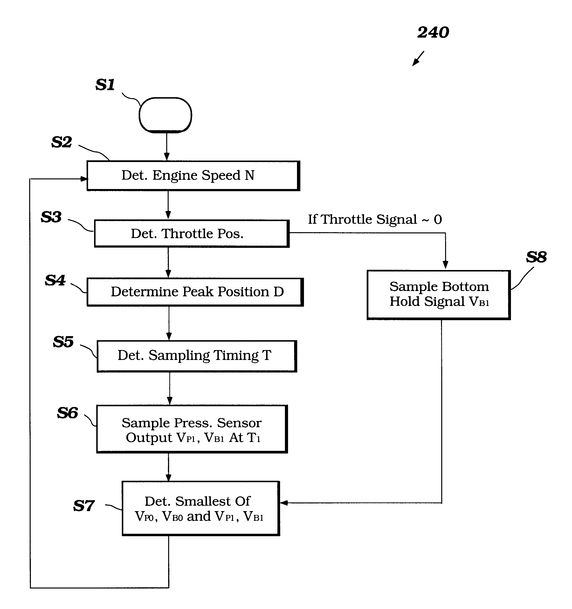
By including a reset portion configured to reset the maintained voltage in the bottom hold device, the bottom hold device can be configured to decay slowly, or not at all, thus more accurately hold the minimum output value from the pressure sensor. Thus, the controller receives a signal that is a more accurate representation of the minimum output of the pressure sensor, thereby allowing the controller to more accurately determine fuel injection duration.
As is known in the art, injecting an air-fuel mixture that is stoichiometrically perfect into an internal combustion engine provides the highest specific power output and the lowest emissions. It is also well known in the art that known internal combustion engines do not reliably produce air-fuel charges with stoichiometrically perfect air-fuel mixtures. Additionally, if an air-fuel charge combusted in an internal combustion engine is excessively "lean," i.e., there is too little fuel in the charge, the engine can be damaged through "detonation," for example. Thus, it is common in the art to configure some charge formers to produce "rich" air-fuel charges. That is, some types of charge formers produce air-fuel charges that have more fuel than an air-fuel charge which is stoichiometrically perfect. Thus, these prior charge formers avoid damaging lean fuel charges by erring on the side of rich fuel charges, thereby protecting the engine but wasting fuel and discharging un-burnt fuel with the exhaust gases.
By constructing an engine in accordance with the present invention, more accurate fuel injection control is possible, thus allowing the engine controller to produce fuel charges that are more stoichiometrically correct, thus reducing fuel consumption and improving emissions of the engine.

Problems solved by technology

Among the various types of data monitored by the controllers of fuel-injected engines, accurate determination of air flow into the engine poses a unique challenge.
However, these flow meters provide additional bulk and make engines more expensive to manufacture.
It is also well known in the art that known internal combustion engines do not reliably produce air-fuel charges with stoichiometrically perfect air-fuel mixtures.
Additionally, if an air-fuel charge combusted in an internal combustion engine is excessively "lean," i.e., there is too little fuel in the charge, the engine can be damaged through "detonation," for example.

Method used


Image

  • Fuel injection control
  • Fuel injection control
  • Fuel injection control

Examples


Embodiment Construction

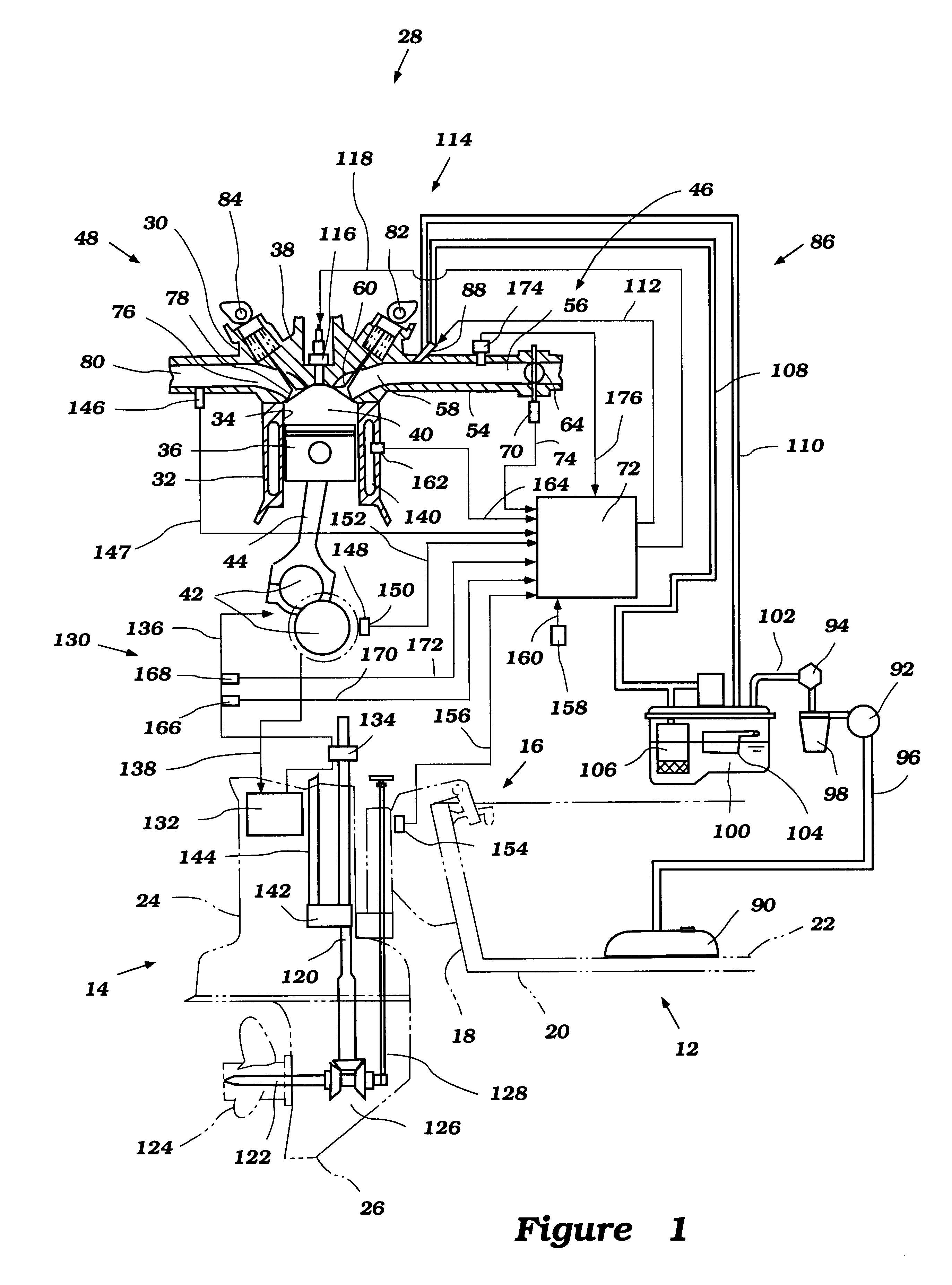
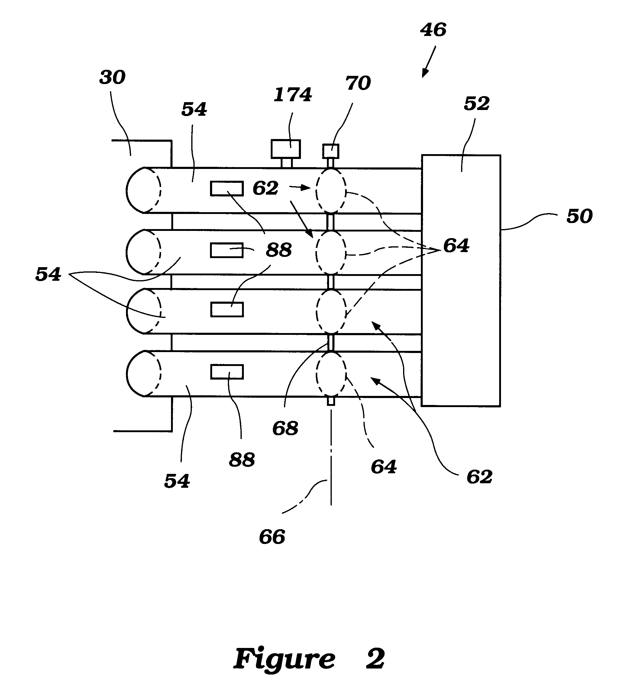
With initial reference to FIG. 1, an outboard motor 10 for powering a watercraft 12 is illustrated. The outboard motor 10 advantageously has an electronic control unit arranged and configured in accordance with certain features, aspects, and advantages of the present invention. The outboard motor 10 provides an exemplary environment in which the electronic control unit has particular utility. The electronic control unit of the present invention may also find utility in applications using internal combustion engines, such as, for example but without limitation, personal watercraft, small jet boats, off-road vehicles, racing vehicles, and heavy construction equipment.

In the illustrated embodiment, the outboard motor 10 comprises a drive unit 14 and a bracket assembly 16. Although schematically shown in FIG. 1, the bracket assembly 16 comprises a swivel bracket and a clamping bracket. The swivel bracket supports the drive unit 14 for pivotal movement about a generally vertically extend...


PUM


Abstract

An engine includes an electronic controller which samples the pressure in the induction system once per rotation of the crankshaft. The controller is configured to determine the minimum voltage signal output by the pressure sensor. The controller then uses the minimum pressure sensed by the pressure sensor to control the fuel injection of the engine. The controller may include two and / or three dimensional maps for predicting the appropriate timing for sampling the pressure sensor. Optionally, the controller may include a bottom hold device for holding a minimum value of the signal output from the pressure sensor, thus corresponding to the minimum pressure sensed by the pressure sensor.

Description

PRIORITY INFORMATIONThis application is based on and claims priority to Japanese Patent Application No. 11-081111, filed Mar. 25, 1999.1. Field of the InventionThe present invention is directed to a controller for an engine, and in particular, a controller for a fuel-injected engine which controls the fuel injectors based on a detected intake air pressure.2. Description of Related ArtIn all fields of engine design, there is an increasing emphasis on obtaining more effective emission control, better fuel economy, and at the same time, continued high or higher power output. This trend has resulted in the substitution of fuel injection systems for carburetors as the charge former for internal combustion engines. Typically, fuel injection systems for internal combustion engines receive input from a variety of sensors included on the engine which are configured to output data which reflect the operating conditions of the engine. For example, a fuel-injected engine may include an engine s...

Claims


Application Information

Patent Timeline
Patent Type & Authority Patents(United States)
IPC IPC(8): F02D41/00F02D41/24F02D41/32F02D41/04F02D45/00
CPCF02D41/2422F02D41/28F02D41/32F02D2250/14F02D2200/0406
Inventor KANNO, ISAO
Owner SANSHIN KOGYO CO LTD
Learn More