Image blur prevention apparatus

a technology of image blur and prevention apparatus, which is applied in the field of image blur prevention apparatus, can solve the problems of remarkably decreasing the possibility of making a photographing failure, taking almost ten seconds, and 45p until dc is completely absorbed

Inactive Publication Date: 2001-07-17
CANON KK
View PDF9 Cites 13 Cited by
  • Summary
  • Abstract
  • Description
  • Claims
  • Application Information

AI Technical Summary

Problems solved by technology

In current cameras, since exposure determining, focusing, and other operations important for photographing are all automated, even for persons unskilled in camera operation, a possibility of making a photographing failure is remarkably decreasing.
However, with the property of cutting 0.1 Hz or less, there is a problem that it takes almost ten seconds from when a blur signal is transmitted from the blur detection device 45p until DC is completely cut.
In this case, it is unfavorable to consume time to change the time constant.
However, as described above, when the time constant changing of the DC cut filter 414p is not completed, the integrating operation is not performed until the completion of the time constant changing.
Furthermore, in the circuit constitution of FIG. 37, since a large-capacity capacitor of 10 pF is used in the capacitor 421p, the circuit is remarkably enlarged, and a problem arises that costs are raised.
Furthermore, when the DC cut filter 48p is constituted in this manner, another problem arises that the blur prevention precision is lowered.
), which is unfavorable also considering from a circuit scale, and a noise respect.
As described above, the current DC cut filter has problems that the capacitor is large and unsuitable for miniaturization and cost reduction and that the blur prevention precision is lowered.

Method used


Image

  • Image blur prevention apparatus
  • Image blur prevention apparatus
  • Image blur prevention apparatus

Examples


first embodiment

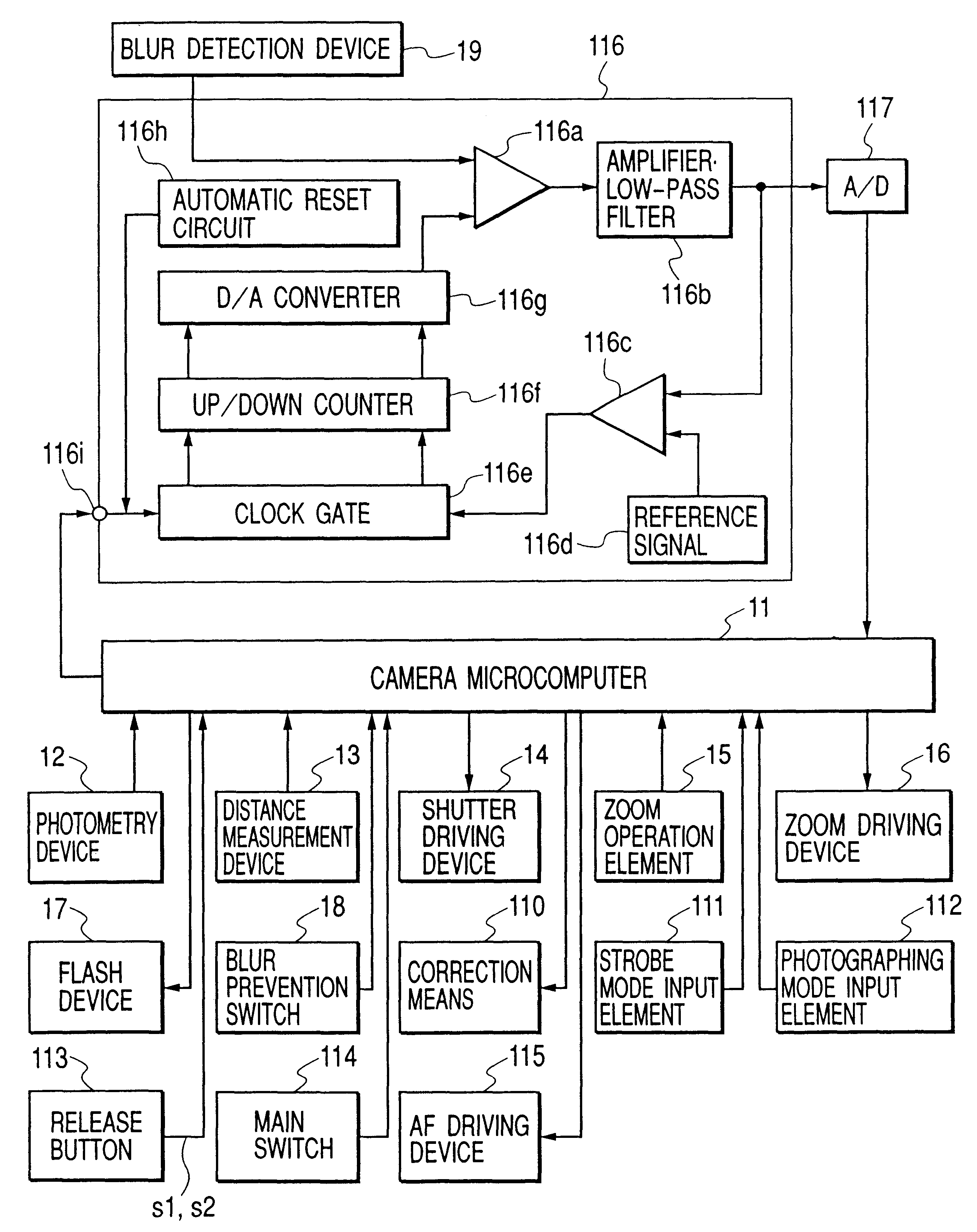
FIG. 1 is a block diagram showing a camera circuit constitution according to the present invention; only a portion associated with the embodiment is shown, and other camera elements are omitted to facilitate the description.

In FIG. 1, upon input of an on-signal of a main switch 114, a camera microcomputer 11 delivers a photographing lens tube from a state of a depressed barrel to a state of an optical system ready for photographing, and additionally opens a lens barrier. In this case, a blur detection device 19 is also started.

From a photographing mode input element 112 a photographing mode selected by a photographer is transmitted to the camera microcomputer 11. For example, photographing modes include a sport mode suitable for photographing subjects moving around, a portrait mode suitable for close-up photographing persons, a macro mode suitable for close-up photographing subjects, and a night view mode suitable for photographing a night view.

From a strobe mode input element 111 a...

second embodiment

In the above-described first embodiment, the blur detection device 19 and the analog processing circuit 116 are separate components. However, since both components are elements necessary for application of blur detection, they may be combined into one for compact construction and easy operation.

FIG. 8 is a block diagram showing the camera main portion constitution according to a second embodiment of the present invention. As shown in the drawing, the blur detection device 19 and the analog processing circuit 116 of the first embodiment are combined into one unit as a blur detection unit 21.

In FIG. 8, the blur detection device 19 is constituted of an image blur detection system 19a and an image blur detection circuit 19b. For example, when the vibratory gyro is used as the blur detection device, the image blur detection system 19a is a vibrator, and the image blur detection circuit 19b is a portion for performing signal processing in which a signal having Coriolis force detected by t...

third embodiment

In the block diagram of FIG. 8, the automatic reset circuit 116h is incorporated in the blur detection unit 21. However, the automatic reset circuit 116h can be omitted in the same manner as in the constitution example of FIG. 5.

FIG. 11 is a block diagram showing the camera main portion constitution according to a third embodiment of the present invention, in which the automatic reset circuit is omitted from the blur detection unit 21, and the signal transmitted directly on the blur detection unit 21 from the release button 113 is also omitted.

When the camera main switch 114 is turned on, the blur detection unit 21 starts operating to start blur detection. At this time, the offset removing operation is not started yet. Subsequently, when the signal indicative of the half depressed release button 113 is transmitted to the camera microcomputer 11, the camera microcomputer 11 outputs the clock signal to the clock gate 116e via the reset terminal 116i, and the blur detection unit 21 sta...


PUM


Abstract

There is disclosed an image blur prevention apparatus which is reduced in size and weight, which is mounted onto an apparatus without deteriorating operations of the apparatuses, and which appropriately and quickly removes the offset signal superimposed onto a blur signal, so that a highly precise blur signal can be output. The apparatus comprises blur detection means for detecting blur, offset signal removing means for removing the offset signal superimposed on the blur signal from the blur detection means, and re-operation instructing means for allowing the offset signal removing means to remove the offset signal again even after offset signal removing is once completed and the blur signal is used to start a digital calculation.

Description

1. Field of the InventionThe present invention relates to an image blur prevention apparatus which prevents image blur caused by hand fluctuation or the like in a camera, an optical apparatus, and the like.2. Description of the Related ArtIn current cameras, since exposure determining, focusing, and other operations important for photographing are all automated, even for persons unskilled in camera operation, a possibility of making a photographing failure is remarkably decreasing.Moreover, in recent years, a system for preventing a hand fluctuation applied to a camera has been researched, and there are almost no factors for inducing photographers' photographing mistakes.Here, the system for preventing the hand fluctuation will briefly be described.The hand fluctuation of the camera during photographing is a vibration whose frequency is usually in the range of 1 Hz to 10 Hz. To allow photographs to be taken without any image blur even if such hand fluctuation is caused at the time o...

Claims


Application Information

Patent Timeline
Patent Type & Authority Patents(United States)
IPC IPC(8): G03B17/00
CPCG03B17/00G03B2217/005
Inventor WASHISU, KOICHI
Owner CANON KK
Why Eureka
Try Eureka