
Apodization methods and apparatus for acoustic phased array aperture for diagnostic medical ultrasound transducer

a phased array aperture and ultrasound transducer technology, applied in the field of diagnostic medical ultrasound imaging, can solve the problems of difficult to achieve apodization of the elevation aperture, image artifacts are difficult to distinguish from true images, and the independent array elements are not perfectly unidirectional transducers, etc., to achieve the effect of reducing side lobes and side lobe image artifacts, and low cos

Inactive Publication Date: 2001-07-10
SIEMENS MEDICAL SOLUTIONS USA INC
View PDF11 Cites 351 Cited by
  • Summary
  • Abstract
  • Description
  • Claims
  • Application Information

AI Technical Summary

Benefits of technology

is to provide a relatively low cost apparatus and method that will achieve the correct apodization to reduce side lobes and side lobe image artifacts by offsetting the negative apodization of an elevation geometric lens.

Problems solved by technology

However, these independent array elements are not perfectly unidirectional transducers, because such transducers frequently have transmission and reception image sensitivities at angles to their main direction sensitivity.
Such image artifacts can be hard to distinguish from true images.
Apodization of the elevation aperture is always difficult to achieve, since the aperture is not normally subdivided in that direction.
The only existing method in the prior art involves subdividing the elevation aperture, which increases the cost and complexity of the associated transducer and system.
Apodization of the azimuthal aperture is either not attempted in low cost ultrasound systems, or is accomplished in higher cost ultrasound systems by expensive electronic circuitry.

Method used


Image

  • Apodization methods and apparatus for acoustic phased array aperture for diagnostic medical ultrasound transducer
  • Apodization methods and apparatus for acoustic phased array aperture for diagnostic medical ultrasound transducer
  • Apodization methods and apparatus for acoustic phased array aperture for diagnostic medical ultrasound transducer

Examples


Embodiment Construction

This invention provides an independent apodization apparatus and method to achieve a desirable aperture apodization function for minimizing side lobes and their artifacts. The following apparatus and method corrects for the reverse apodization from an ultrasound transducer probe lens, and by design can achieve any desirable apodization function (e.g., Hamming, Hanning, raised cosine, or other functions). These apodization functions are discussed in Chapter 10, Angular Accuracy and Resolution, and Chapter 12, Adaptive Nulling, of Principles of Aperture System Design, by B. Steinberg, John Wiley and Sons (1976), hereby incorporated by reference.

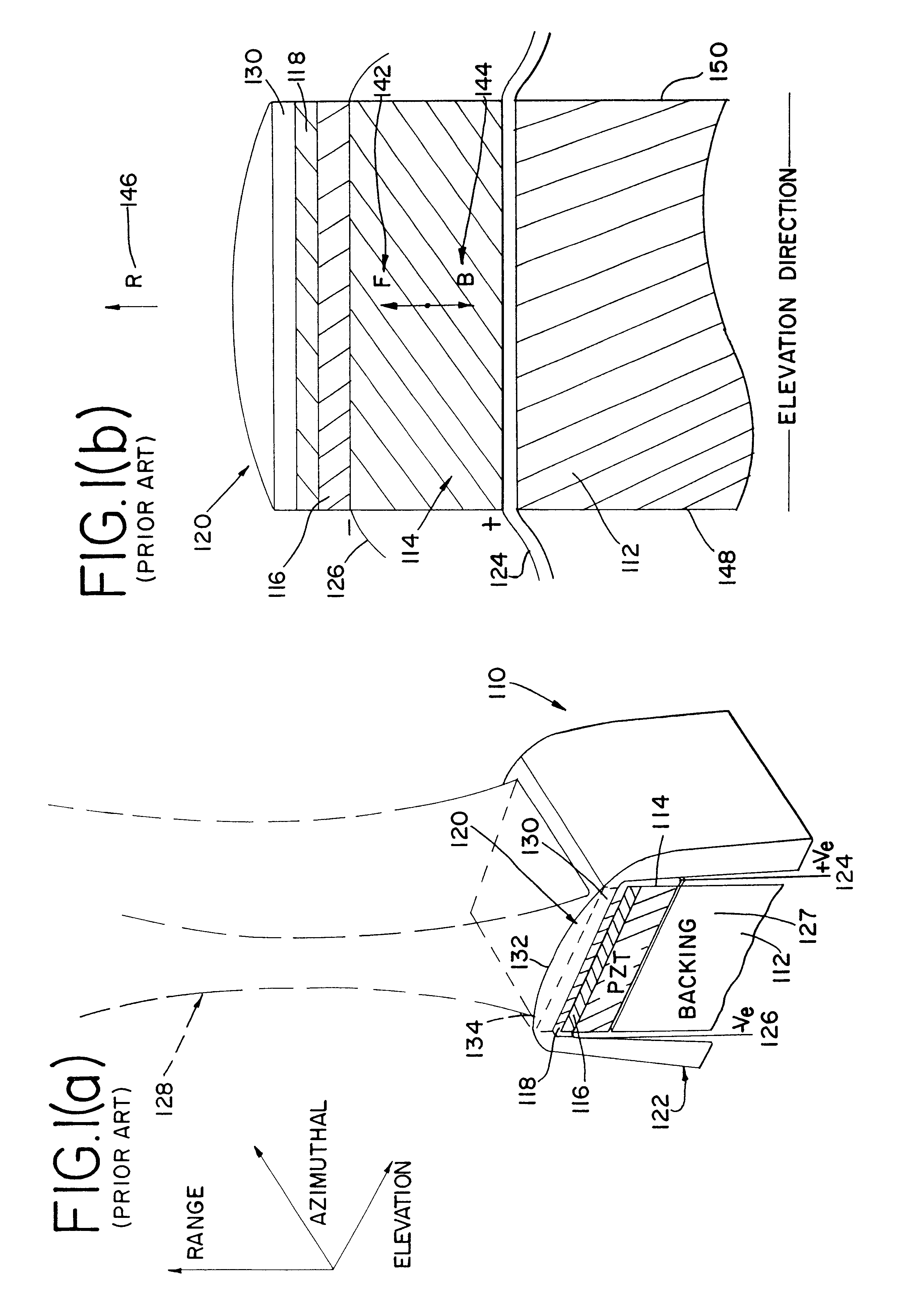
FIG. 1(a) shows a partial perspective view, cut away to reveal a crosssection taken along the elevation direction, of a conventional ultrasound transducer probe assembly 110 with plastic housing 122, with room temperature vulcanizing silicone rubber (RTV) geometric lens 120 in the ultrasound beam path. FIG. 1(a) also shows radiation pattern 128...


PUM

PropertyMeasurementUnit
Fractionaaaaaaaaaa
Fractionaaaaaaaaaa
Fractionaaaaaaaaaa

Abstract

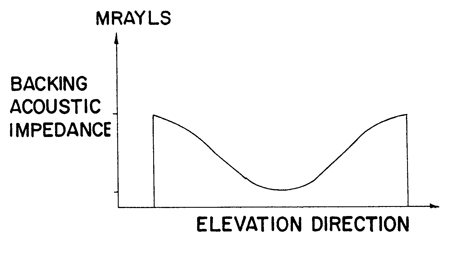
An apparatus and method using a backing block having a variable acoustic impedance as a function of elevation or azimuth, to achieve a desirable apodization of the aperture of an ultrasound transducer stacked with the backing block. The backing block has a gradient profile in acoustic impedance that changes from a minimum value to a maximum value along the elevation direction and / or azimuthal direction of the stacked ultrasound transducer. Typically, the backing block has an elevation gradient profile in acoustic impedance that increases from a minimum value of acoustic impedance near the center of the backing block to a maximum value of acoustic impedance at opposing lateral faces of the backing block. The backing block can be discretely segmented in acoustic impedance, with as many segments as are practically manufacturable. An individual segment can have a uniform or variable acoustic impedance. The backing block can be continuous in acoustic impedance, with a minimum acoustic impedance in the center and a maximum acoustic impedance at two or more planar lateral faces.

Description

1. Field of the InventionThis invention relates generally to an improvement in diagnostic medical ultrasound imaging, and more specifically to reducing elevation side lobe image artifacts.2. Description of the Prior ArtThere is growing interest in 2-D ultrasound images for medical applications. Medical ultrasound systems are described in U.S. Pat. No. 5,570,691, U.S. Pat. No. 5,667,373, U.S. Pat. No. 5,685,308, U.S. Pat. No. 5,827,188 and U.S. Pat. No. 5,882,307 to Wright, et al.; and U.S. Pat. No. 5,856,955 and U.S. Pat. No. 5,675,554 to Cole, et al. The theory of medical ultrasound imaging is extensively discussed in Physics and Instrumentation of Diagnostic Medical Ultrasound, by Peter Fish, pp. 1-189 (1990).A medical ultrasound system includes a transmit beamformer to send electrical signals to an ultrasound transducer, which converts these electrical signals into acoustic pressure waves. The ultrasound transducer also converts received acoustic pressure wave signals into electr...

Claims


Application Information

Patent Timeline
IPC IPC(8): B06B1/06G01S7/52G10K11/00
CPCB06B1/0685G10K11/002G01S7/52017Y10T29/42
Inventor HANAFY, AMIN M.
Owner SIEMENS MEDICAL SOLUTIONS USA INC
Learn More