
Sliding mount for securing a plastics motor vehicle body part piece on a support

a technology for motor vehicles and parts, applied in the field of sliding mounts, can solve the problems of brittleness, not very flexible, and brittleness of bodywork parts made of plastic materials, and achieve the effect of convenient engagement and easy placemen

Inactive Publication Date: 2001-07-10
CO PLASTIC OMNIUM
View PDF9 Cites 9 Cited by
  • Summary
  • Abstract
  • Description
  • Claims
  • Application Information

AI Technical Summary

Benefits of technology

The present invention seeks to provide a novel sliding mount which presents the advantages of being easy to put into place on a bodywork part, and of prepositioning itself relative to said part so as to facilitate the engagement of members for mounting the bodywork part in their housings, without representing the above-mentioned drawbacks.
Preferably, the area of the spacer that bears against the support is large enough to prevent any creep of the spacer, including when its temperature is high.
In a particular embodiment, the spacer has tabs for holding the thin wall within the thickness of the spacer, and one of the longitudinal edges of the opening has one or more notches shaped to correspond to the shape of the tab(s) of the spacer, thereby enabling the spacer to be put into place in the opening.
According to the invention, the privileged position of the spacer relative to the opening is such that the spacer can move inside the opening in a first direction to compensate for post-shrinkage of the thermoplastic material, and in a second direction, opposite to the first, to compensate for differential expansion between the part made of thermoplastic material and the support.

Problems solved by technology

However, bodywork parts made of plastics material withstand such treatment less well, particularly the baking treatment for paintwork.
As a result the bodywork parts made of plastics material deform and warp or form corrugations that spoil the appearance of the vehicle.
Finally, another problem arises because of the shrinkage to which thermoplastics material parts are subject after a rise in temperature and over time, which phenomenon is known as "post-shrinkage", giving rise to bodywork parts moving relative to the structure of the vehicle, independently of phenomena of differential expansion.
That sliding mount gives rise to various problems which are associated with the presence of said spring blades.
Furthermore, the plastics material used for making the sliding mount is preferably creep-resistant, thereby making it rather brittle and not very flexible, whereas the spring blades need on the contrary to be elastically deformable.

Method used


Image

  • Sliding mount for securing a plastics motor vehicle body part piece on a support
  • Sliding mount for securing a plastics motor vehicle body part piece on a support
  • Sliding mount for securing a plastics motor vehicle body part piece on a support

Examples


Embodiment Construction

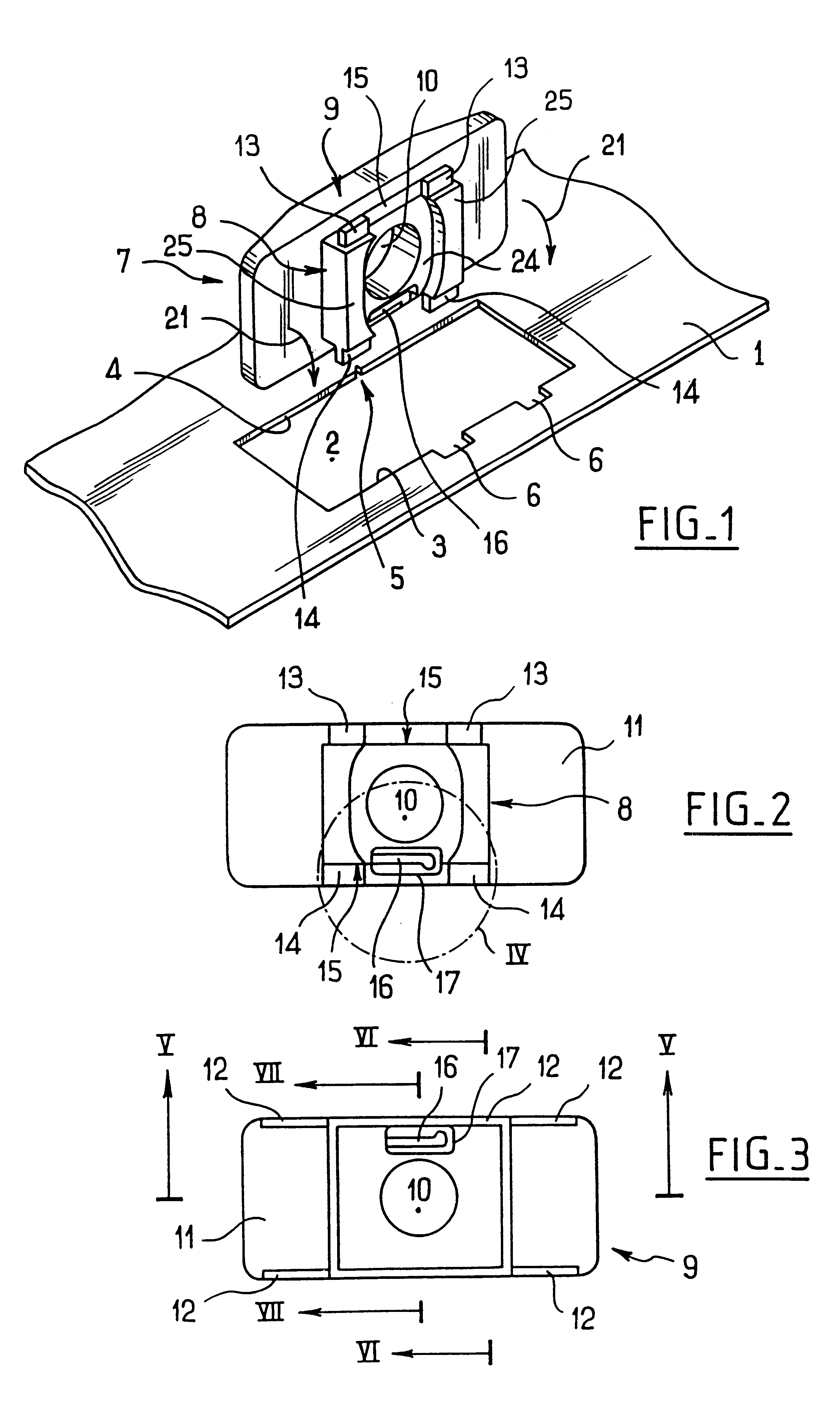
In FIG. 1, there can be seen a portion of a bodywork part 1 of plastics material which comprises a thin wall for mounting in sliding manner to a support (not shown).

An elongate opening 2 of rectangular shape is made through the thin wall. The opening is defined by two substantially parallel longitudinal edges 3 and 4.

An indentation 5 is made in the thickness of one of the longitudinal edges 4, and two notches 6 are formed in the other longitudinal edge 3.

A mount 7 for installing in the opening comprises a spacer-forming portion 8 whose thickness is greater than the thickness of the thin wall, and which is suitable for sliding inside the opening 2 in its longitudinal direction, and a head 9 which projects from the spacer 8 all around it and which is wider than the opening 2 so as to be incapable of passing through it.

The mount 7 has a central bore 10 perpendicular to its general plane and designed to receive anchor means (not shown) such as a screw for securing the mount to the suppo...


PUM


Abstract

A sliding mount for a part made of plastics material and having at least one thin wall that is to be mounted in sliding manner on a support via its thin wall, the thin wall having an elongate opening therein with two longitudinal edges that are substantially parallel at least over a portion of their length, the mount comprising a spacer that is separate from the part, that is thicker than the thin wall, and that is suitable for sliding in the opening between the two longitudinal edges thereof. The spacer comprises an elastically deformable portion bearing slidably against the thin wall of the part when the spacer slides in the opening, the thin wall having a coupling shape organized in such a manner that when the spacer is in a privileged position relative to the opening, the deformable portion of the spacer couples with the thin wall.

Description

The present invention relates to a plastics material piece suitable for being mounted in sliding manner on a support.Motor vehicle bodywork parts are secured to the structure of the vehicle by add-on mounts which hold them in position throughout all stages of manufacture of the vehicle subsequent to them being put into place, and also throughout the lifetime of the vehicle.The steps in vehicle manufacture subsequent to bodywork parts being put into place include the step of electrophoresis which consists in immersing the entire vehicle, including its bodywork parts, in a bath, and then passing the vehicle through an oven at a temperature lying in the range about 180.degree. C. to 220.degree. C. so as to treat the structure of the vehicle and all of the metal parts it includes against corrosion, and also a painting step which comprises a stage of baking at a temperature lying in the range about 140.degree. C. to 170.degree. C.Those various operations are designed for bodywork parts m...

Claims


Application Information

Patent Timeline
IPC IPC(8): B62D29/00B62D29/04
CPCB62D29/048Y10T403/606Y10T403/21Y10T403/7015
Inventor GOBLED, PATRICEJACQUEMARD, CLAUDECOURTOIS, SEBASTIENROSSETTO, MARC
Owner CO PLASTIC OMNIUM
Learn More