
Read/write head including displacement generating means that elongates and contracts by inverse piezoelectric effect of electrostrictive effect

a technology of electrostrictive effect and displacement generation means, which is applied in the direction of head disposition/mounting, maintaining head carrier alignment, instruments, etc., can solve the problems of track misregistration, thermal expansion and extraneous, and erasure of signal information stored upon recording

Inactive Publication Date: 2001-06-12
TDK CORPARATION
View PDF12 Cites 212 Cited by
  • Summary
  • Abstract
  • Description
  • Claims
  • Application Information

AI Technical Summary

Problems solved by technology

A problem with a magnetic disk drive is a track misregistration that is an offset between the magnetic head and the recording tracks caused by vibrations of the disk medium surface in synchronism or a synchronism with the rotation of the disk medium, eccentricity of the disk medium, thermal expansion and extraneous vibrations of the magnetic disk drive including the magnetic head and disk medium, etc.
This track misregistration leads to problem, for instance, erasion upon recording of signal information stored in adjacent tracks due to overwriting, a drop upon reproduction of the level of signals outputted from the track concerned, and a quality drop of output signals due to the entrance of signals from adjacent tracks in the form of crosstalk noises.
A grave problem attendant to the conventional magnetic disk drive is, however, that there is a limit in positioning precision, especially recording track-following precision due to the swing motion of the whole of a massive structure comprising the magnetic head, arm and coil, the movement of the slider via the resilient suspension, and the fact that the bearing providing the center of the swing motion has in itself friction resistance, eccentricity, and so on.
For these reasons, the problems associated with a conventional magnetic head positioning mechanism become even more troublesome.
As the read / write track pitch becomes as narrow as about 1 .mu.m while such a flying height is maintained, however, several problems arise, for instance, erasion upon recording of signal information stored in adjacent tracks due to a recording magnetic field leakage, and an S / N degradation upon reproduction due to a drop of signal level absolute output.
As the flying height decreases, however, it is required to more severely control the flying characteristics (fluctuations in the flying height) of the magnetic head upon seek control or read / write track-following control, and the smoothness of the disk medium.
For these magnetic heads taking aim at achieving much higher recording densities, it is very difficult to conduct seek control or read / write track-following control.
However, this approach, too, is unavoidably affected by vibrations of the suspension because the slider is driven via the suspension having resiliency as in the case of the aforesaid VCM positioning mechanism.
Thus there is a limit in positioning precision improvements.
However, it is found that with the electrostatic force actuator it is difficult to generate driving force large enough to displace the slider, and with the electromagnetic force actuator there is concern that the magnetic signal on a disk medium is affected by flux leakage.
A problem common to both actuators is that they are sensitive to extraneous disturbances because the slider must be held in place by means of a support member that has small resiliency and can be deformed by electrostatic force, and electromagnetic force generated from the actuators.
Nonetheless, the magnetic head is susceptible to displacement in the flying direction (fluctuations in the flying height) due to assembly errors, etc.
Assembly steps required for the assembly structure incur some considerable cost, and the assembly structure renders it difficult to increase its rigidity, resulting in a mechanical robustness drop problem associated with bonded parts.
In addition, the assembly structure becomes poor in displacement characteristics due to the need of drawing interconnecting lines out of the electrodes of the piezoelectric elements, and costs much as well thanks to its complexity.
The third embodiment, too, poses similar problems, for instance, variations in displacement characteristics due to assembly errors.
For such a structure, it is difficult to place the size of the displacement generating means and the size of the spaces in which they are fitted under tolerance control.
For piezoelectric elements having a very small displacement amount, it is undesirable that a gap exists between them because there is loss or a variation of the amount of displacement transmitted, or otherwise no displacement is transmitted to the actuator whatsoever.
To eliminate such a gap, high-precision assembly techniques are need, but not only do they involve technical difficulties but incur some considerable expense as well.
In addition, no sufficient robustness is achievable because some load is applied on the piezoelectric element, resulting in a reduction of its life, and a premature degradation of its performance.
When an adhesive layer usually comprising an organic resin, etc. is used for the bonding of the piezoelectric element, the following problems arise.
Transmission loss occurs because the displacement of the piezoelectric element gives rise to deformation of the adhesive layer; bonding reliability drops because some load is applied on the adhesive layer upon the displacement of the piezoelectric element; and displacement transmitted from the piezoelectric element to the electromagnetic transducer element through the adhesive layer is susceptible to a secular change because the adhesive force (fixing force), and rigidity of the adhesive layer changes depending on the aforesaid load, and ambient conditions (high temperature, high humidity, and so on).
In this arrangement, too, there is again a reliability drop because the piezoelectric elements deflect the metal thin sheets through an adhesive layer.
A problem with this flying head is, therefore, that the size of the piezoelectric element must be increased to increase the amount of displacement of the head body.
Another problem with this flying head is that a part of the flying surface is susceptible to deformation, and displacement as well.
This leads to further problems that the flying characteristics are unstable, and the read / write characteristics are unstable as well due to fluctuations in the spacing between the head body and the medium.
Accordingly, when positioning is effected with respect to recording tracks, the same problems as mentioned with reference to the flying type magnetic head arise.

Method used


Image

  • Read/write head including displacement generating means that elongates and contracts by inverse piezoelectric effect of electrostrictive effect
  • Read/write head including displacement generating means that elongates and contracts by inverse piezoelectric effect of electrostrictive effect
  • Read/write head including displacement generating means that elongates and contracts by inverse piezoelectric effect of electrostrictive effect

Examples


Embodiment Construction

Features and advantages of the read / write head according to the present invention will now be explained specifically with reference to a magnetic head.

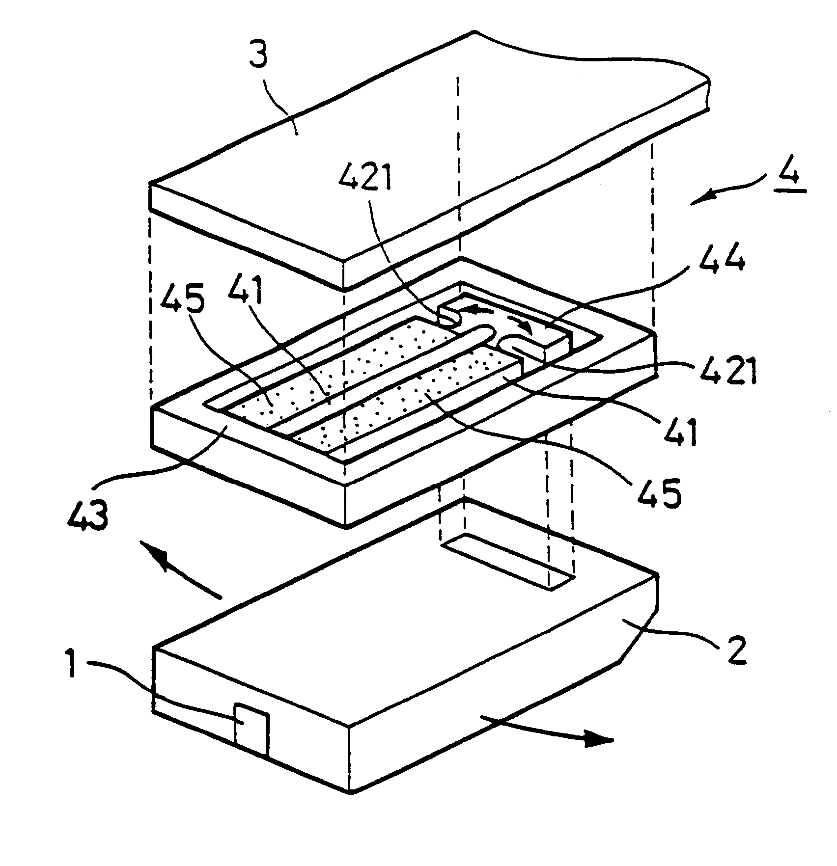
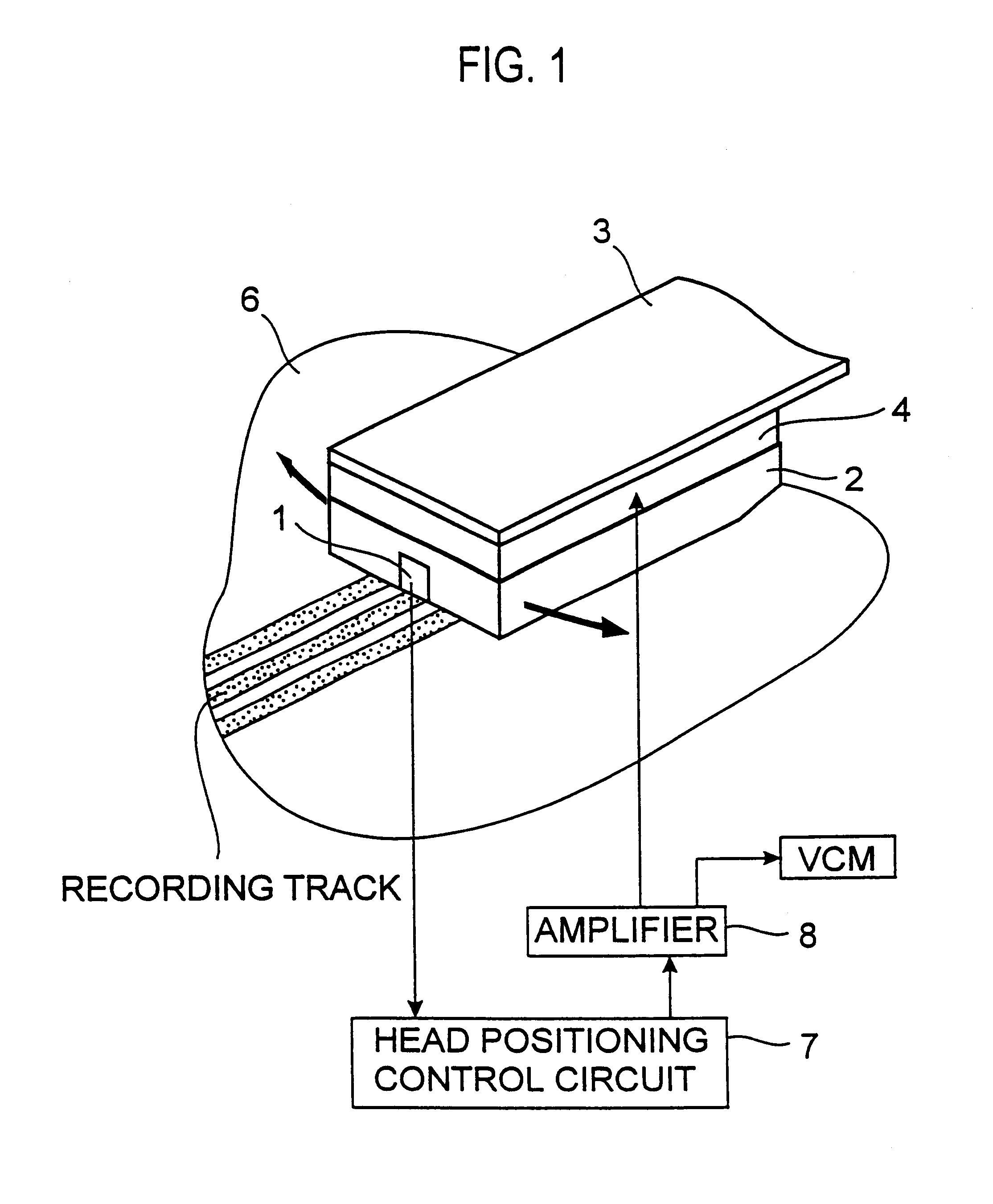
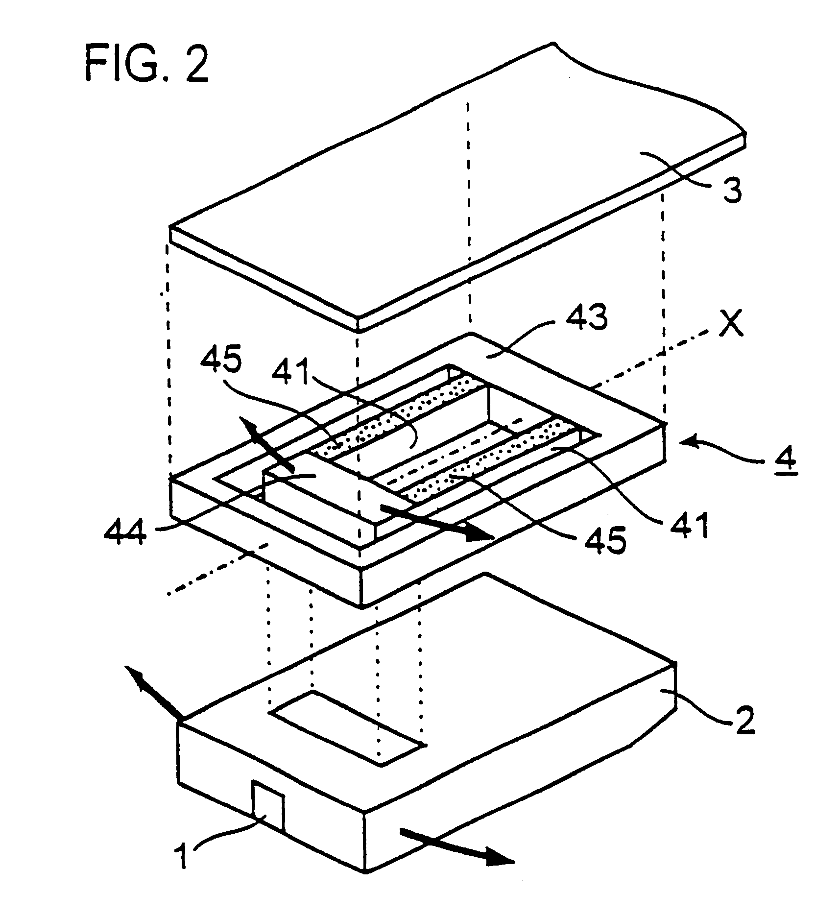
One exemplary structure of the magnetic head according to the present invention is illustrated in FIG. 1. An actuator 4 is located between a slider 2 having an electromagnetic transducer element 1 and a suspension 3 to make connections between them. The actuator 4 is provided with at least one piezoelectric or electrostrictive material layer having electrode layers on both sides. In the present invention, this layer acts as a displacement generating means. The displacement generating means generates elongation and contraction motions by inverse piezoelectric effect or electrostrictive effect. The elongation and contraction motions in turn cause the displacement of the slider 2 relative to the suspension 3. At this time, the slider 2 is coupled to the actuator 4 in such a direction that the direction of displacement of the electromagne...


PUM


Abstract

A read / write head includes a slider provided with an electromagnetic transducer element (or an optical module), an actuator, and a suspension. The actuator includes a fixed part, a movable part, and at least two beam members for coupling them together. The beam members have a displacement generating means that elongates and contracts by inverse piezoelectric effect or electrostrictive effect. The fixed part is fixed to the suspension, and the movable part is fixed to the slider. Upon the elongation and contraction of the displacement generator, the displacement generator deflects and the movable part displaces linearly, circularly or rotationally with respect to the fixed part, and the electromagnetic transducer element displaces in a linear or circular orbit, so that the electromagnetic transducer element intersects recording tracks. In the actuator, the fixed part, movable part and beam members are formed as an integrated single piece by providing a hole and / or a cutout in a sheet-like member constructed of a piezoelectric or electrostrictive material. The actuator of the structure illustrated is used for the positioning of a direction intersecting recording tracks. In this case, the total sum of voltages applied on the displacement generating means is controlled in such a manner that it is constant at any time, thereby controlling position fluctuations of the electromagnetic transducer element in the direction vertical to the recording medium surface.

Description

The present invention relates to a read / write head, a read / write head positioning mechanism, and a read / write system such as a magnetic or optical disk drive.DISCUSSION OF THE BACKGROUNDFIG. 32 is a plan schematic illustrative of a flying type magnetic head and a positioning mechanism therefor used in a conventional magnetic or hard disk drive (HDD).As shown in FIG. 32, the magnetic head is built up of a slider 2 having an electromagnetic transducer element 1, and a suspension 3 for supporting the slider 2. For the purpose of simplification, interconnecting lines to make electric connections between the electromagnetic transducer element 1 and a signal processing circuit in the hard disk drive for the transmission of read / write signals are not illustrated.A VCM (voice coil motor) 5 is used in an actuator for magnetic head positioning. The VCM 5 is built up of a coil 51, a permanent magnet 52, a bearing 53 and an arm 54. The arm 54 is provided with the coil 51 at one end and with the...

Claims


Application Information

Patent Timeline
IPC IPC(8): G11B21/20G11B21/10G11B5/55G11B5/58G11B7/09
CPCG11B5/5552G11B5/58G11B5/59627G11B7/0937G11B21/10G11B21/20
Inventor SOENO, YOSHIKAZUICHIKAWA, SHINJITSUNA, TAKAMITSUSATO, ISAMU
Owner TDK CORPARATION
Learn More