
Sprinkler or spray head

a spray head and spraying technology, applied in fire rescue and other directions, can solve the problems of high momentum and penetration capacity, hampered spring properties and operation, and the loss of speed and momentum of the spraying medium as the droplets grow in siz

Inactive Publication Date: 2001-05-15
MARIOFF CORP OY
View PDF11 Cites 23 Cited by
  • Summary
  • Abstract
  • Description
  • Claims
  • Application Information

AI Technical Summary

Benefits of technology

The primary object of the present invention is to provide a new sprinkler or spray head which does not involve the above drawbacks. The secondary object of the invention is to provide a sprinkler or spray head that allows the liquid flow to increase more with the increase in pressure than the earlier solutions by providing a structure that essentially changes the resistance value, so-called k-value, of a nozzle as the pressure changes.
The main advantages of the sprinkler according to the invention are that the sprinkler allows spraying of extinguishing medium without hindrance with a great force, penetration and momentum when the release means has been released. Further, a preferred embodiment of the invention allows the liquid flow of extinguishing medium to increase heavily as the pressure of the extinguishing medium increases.

Problems solved by technology

The problem in the sprinklers of the above type is that the holder or some other part of the sprinkler always operates as an extinguishing-medium distributor, thus resisting the jet of extinguishing medium.
If the extinguishing medium is water mist and the water mist hits the holder, the jet of extinguishing medium loses speed and momentum as the droplets gain in size.
This is usually a drawback, since the aim is to spray water mist with a very small droplet size and, according to modern fire fighting technology, with high momentum and penetration capacity.
Whether or not the mechanism operates can be considered uncertain as the sprinkler has been unused for years, and, for example, the locking mechanism has dirtied and corrosion may have hampered the properties and operation of the spring.

Method used


Image

  • Sprinkler or spray head
  • Sprinkler or spray head
  • Sprinkler or spray head

Examples


Embodiment Construction

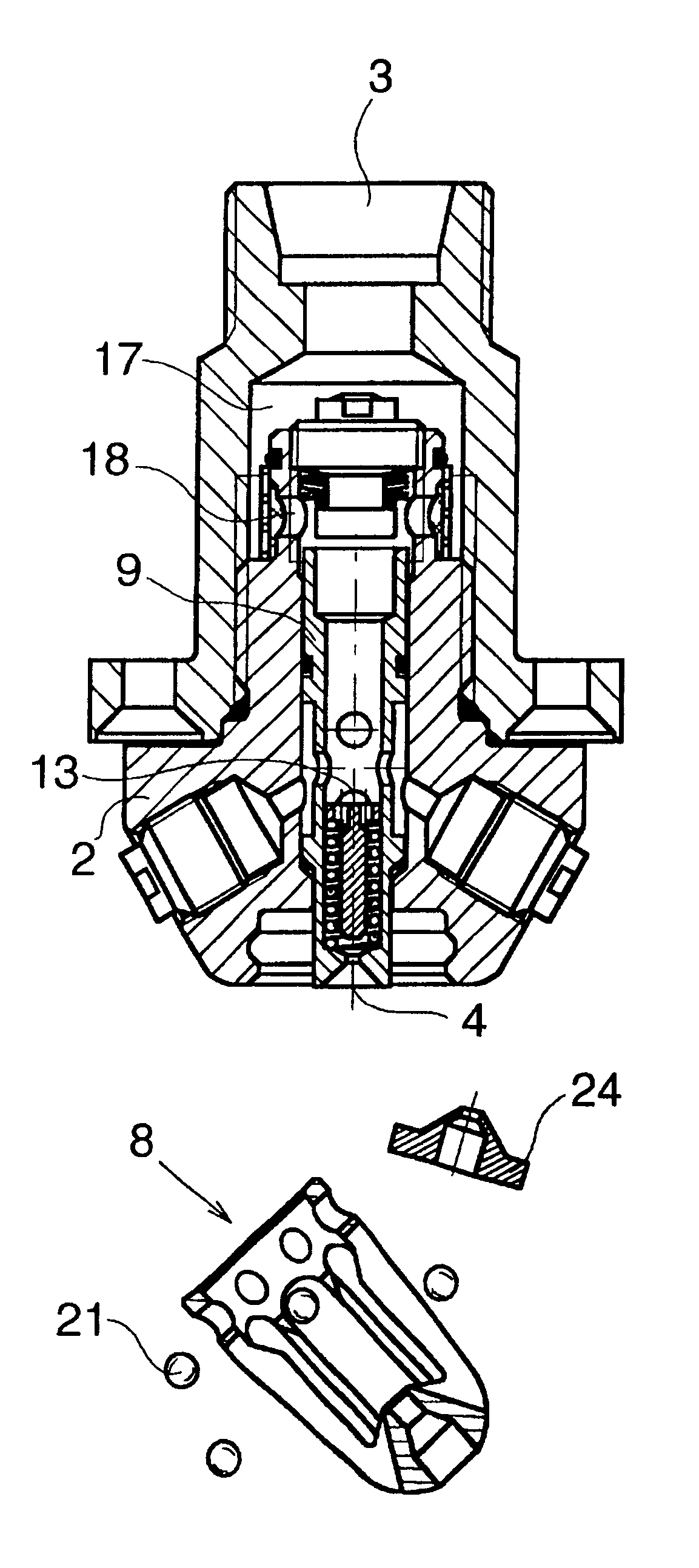
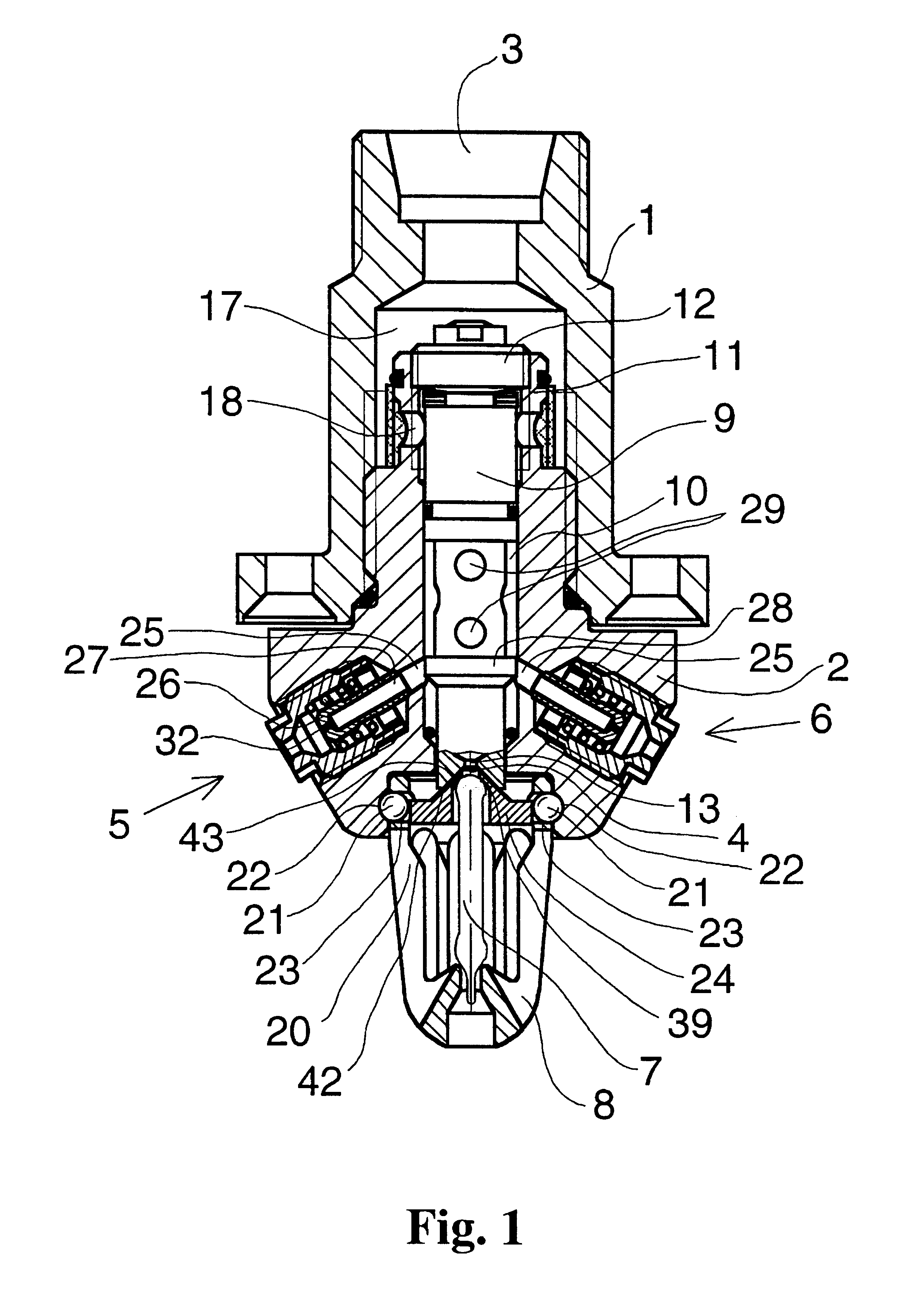
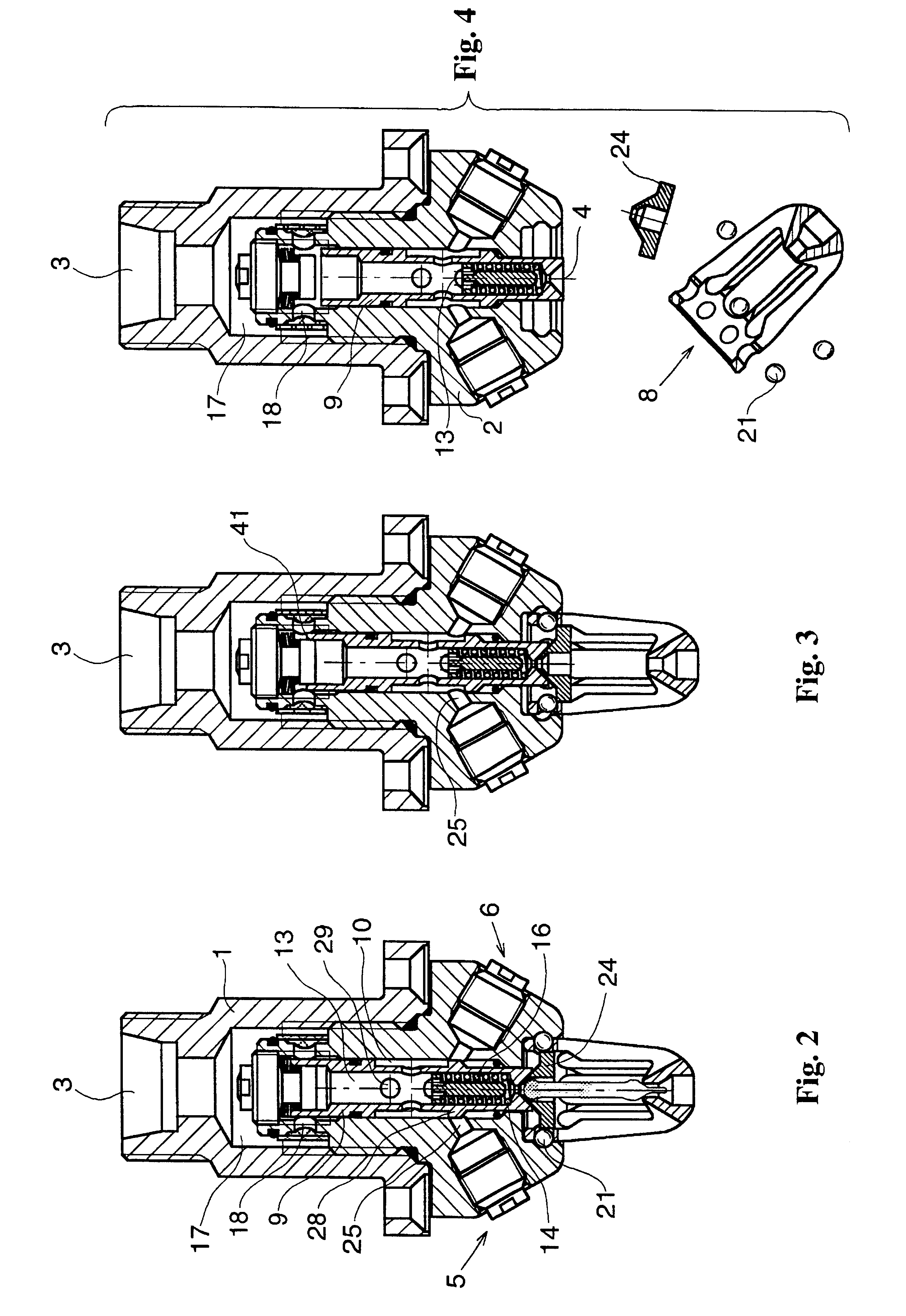
FIG. 1 shows a sprinkler comprising a mounting element 1, a housing 2 screwed into the mounting element, an inlet 3, a central nozzle 4, a number, for example 2 to 8, of obliquely arranged nozzles 5, 6 and a release means, which is a glass ampoule 7 or the like, which will explode or melt at a high temperature, releasing the sprinkler. The ampoule 7 is mounted in a holder 8 positioned in front of the nozzle so that the lower end of the ampoule rests on the free end of the holder and the upper end of the ampoule rests on the nozzle 4. The holder 8 has openings on the side, whereby the ampoule is able to react quickly to a rising temperature.

The inlet 3 is situated in the mounting element 1 for mounting the sprinkler, for example, in the ceiling.

In the housing 2 is mounted a spindle 9, which is arranged to slide in a conduit 10 provided in the housing. A spring, preferably a cup spring 11 strained between the spindle and an end part 12 in the housing 2 is arranged to exert a force in ...


PUM


Abstract

The invention relates to a sprinkler or a spray head comprising a housing (2), an inlet (3), a nozzle (4) mounted in the housing, a passage (17-18-13) from the inlet to the nozzle, and a holder (8) for a release means, the holder being mounted in front of the nozzle so that it prevents the nozzle from spraying extinguishing medium forward without hindrance, the nozzle being arranged to spray extinguishing medium once the release means has been released. The holder (8) is mounted in the housing (2) by means of a locking mechanism, which is arranged to open and release the holder (8) from the housing once the release means (7) has been released. To allow efficient and forceful spraying of the extinguishing medium without that the holder stands in the way, reducing the momentum and penetration force of the jet, and to safeguard the operation, the spinkler or spray head comprises a spindle (9) which is arranged to move in the housing (2) from a first position, in which the spindle is arranged to close the passage (17-18-13) to keep the nozzle (4) closed, to a second position, in which the spindle is arranged to open the passage to keep the nozzle open, when the release means is being released, the spindle being arranged to exert a force on the locking mechanism and to open the locking mechanism when the spindle is moved toward the holder (8) into the second position, whereby the nozzle (4) can forcefully spray the extinguishing medium forward essentially without hindrance.

Description

BACKGROUND OF INVENTIONThe invention relates to a sprinkler or a spray head comprising a housing, an inlet, a nozzle mounted in the housing, a passage from the inlet to the nozzle, and a holder for a release means, the holder being mounted in front of the nozzle so that it prevents the nozzle from spraying extinguishing medium forward without hindrance, the nozzle being arranged to spray extinguishing medium once the release means has been released, the holder being mounted in the housing by means of a locking mechanism, which is arranged to open and release the holder from the housing once the release means has been released.The problem in the sprinklers of the above type is that the holder or some other part of the sprinkler always operates as an extinguishing-medium distributor, thus resisting the jet of extinguishing medium. Yet it is often desired that the nozzle can spray extinguishing medium without hindrance once the sprinkler has been released. If the extinguishing medium i...

Claims


Application Information

Patent Timeline
IPC IPC(8): A62C37/08A62C37/14A62C35/68A62C37/10
CPCA62C37/14A62C31/05
Inventor SUNDHOLM, GORAN
Owner MARIOFF CORP OY
Learn More