
Endcaps for fiberglass running boards

a running board and end cap technology, applied in the direction of building components, building reinforcements, constructions, etc., can solve the problems of affecting the strength of the cured resin that bonds the glass fibers together, the end of the beam constructed from the fiberglass rail can also form undesirable splinters and cracks, and the use of the fiberglass running board is limited, so as to improve the strength, economy and durability of such materials.

Inactive Publication Date: 2001-04-24
HOLLAND CO
View PDF5 Cites 20 Cited by
  • Summary
  • Abstract
  • Description
  • Claims
  • Application Information

AI Technical Summary

Benefits of technology

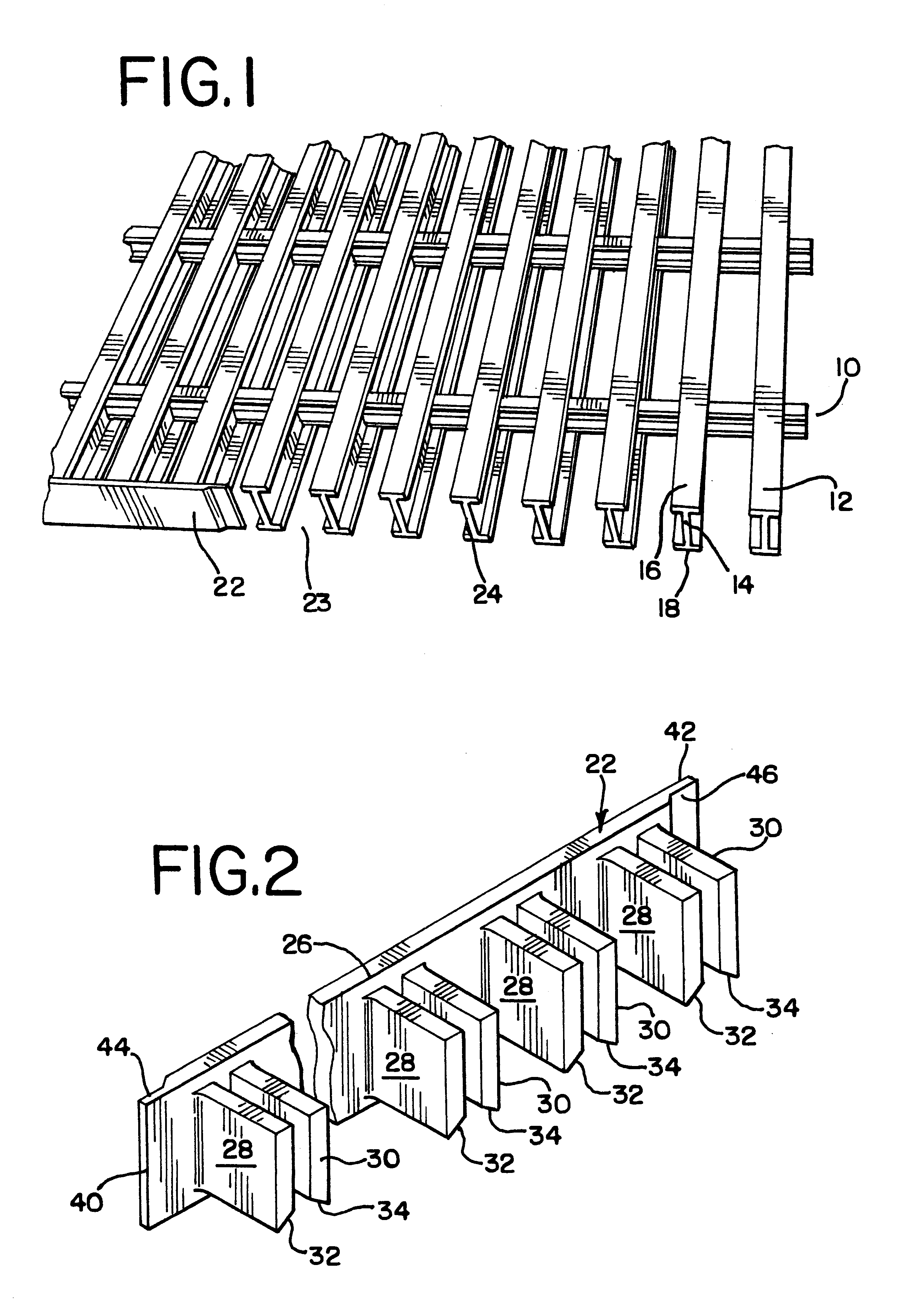
The present invention is an endcap particularly adapted for use on a plurality of beams that form a rail car running board. These beams are typically beams having an I-shaped cross section formed by a vertical web portion and two transversely oriented flanges centered along the top and bottom edges of the vertical web portion. The beams are arranged and connected in parallel fashion to form the running board. Beams of this type can also be used to form a platform deck or running board of a vehicle, semi-trailer, marine vessel, or the like. The beams can also provide a platform for use as an industrial catwalk or any other platform application. The endcaps are advantageous in closing the ends of running boards constructed from fiberglass reinforced plastic beams, thereby complementing the strength, economy and durability of such materials. The endcaps provide a closure for the edges of the running board formed by the terminal ends of the beams, thereby protecting the beam ends from damage and providing safety to persons from the exposed beam ends of the edge of the running board.
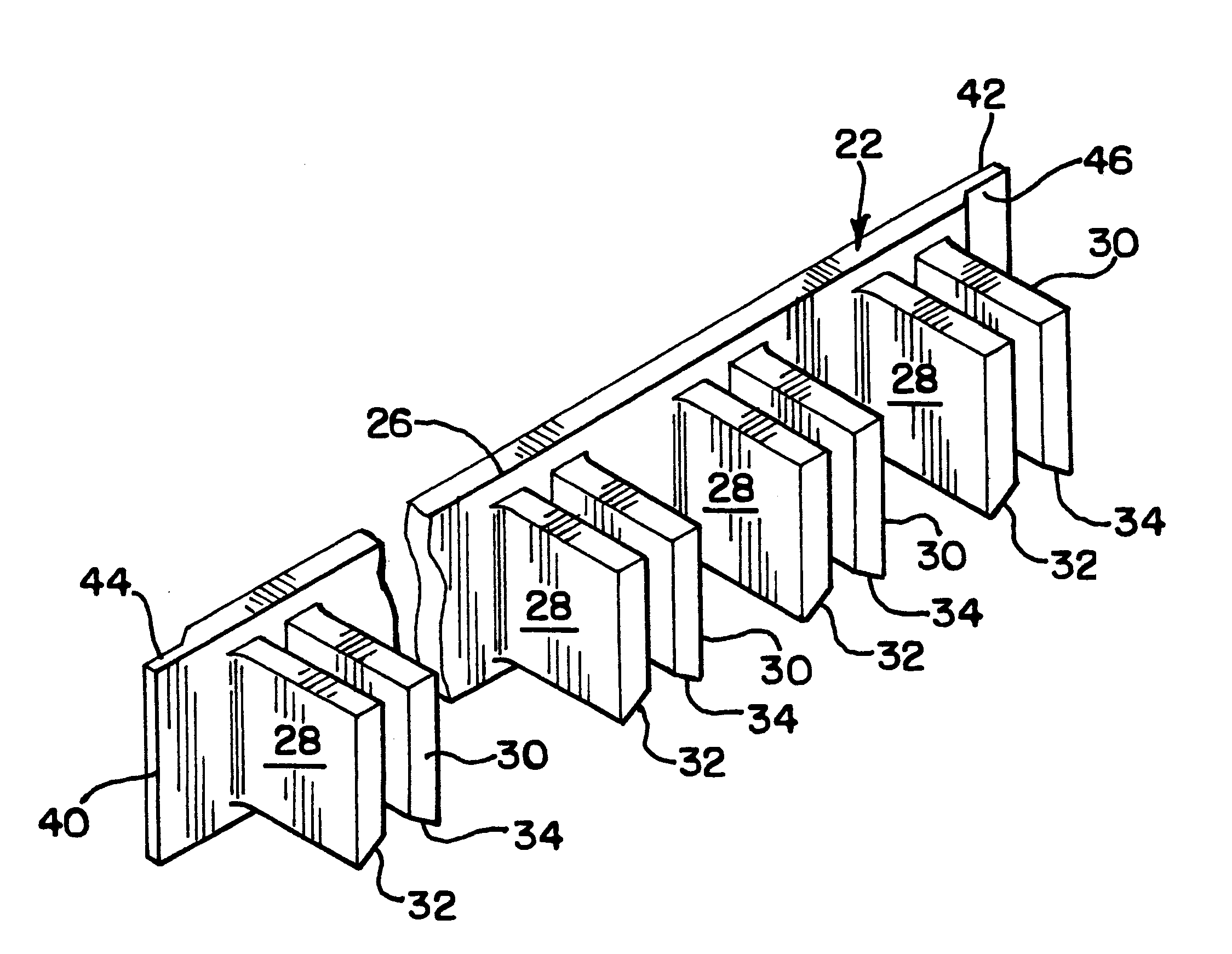
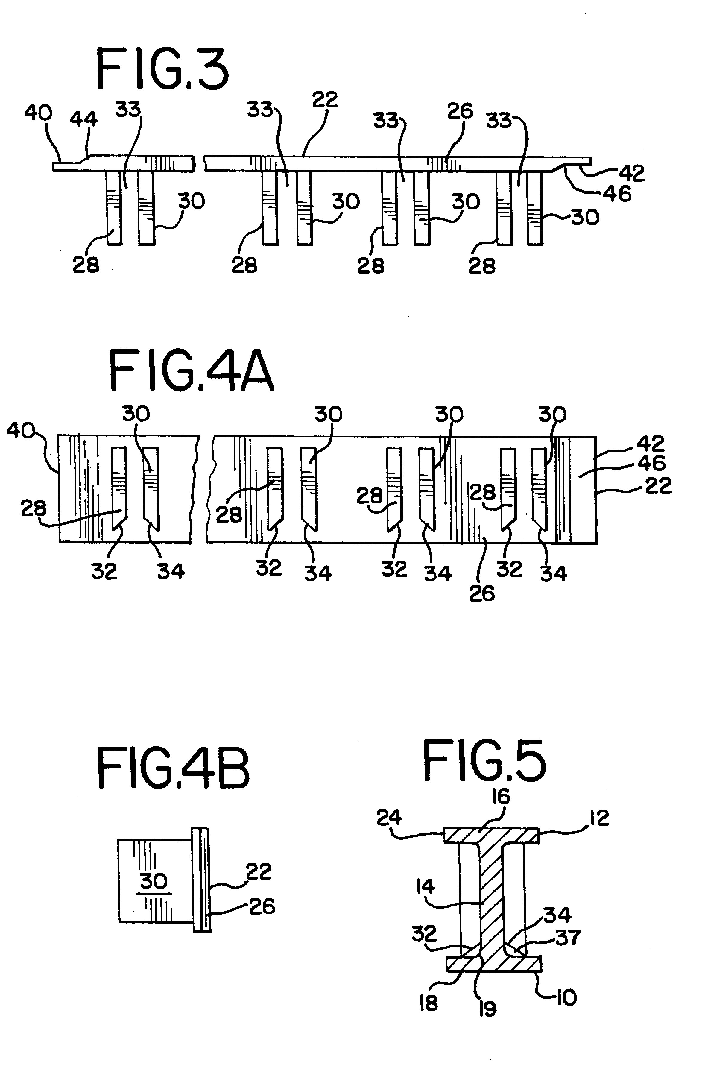
Each endcap comprises a generally rectangular elongated base web portion having a plurality of paired transversely projecting flange fingers of a generally rectangular planar configuration. The paired flange fingers are vertically arranged along the length of the base web portion. The paired flange fingers are parallel to each other and form a gap therebetween. Each pair of flange fingers are spaced apart from other pairs to allow corresponding engagement with each end of spaced apart beams of a running board edge. When the endcap is installed, the flange fingers are positioned such that the gaps between each flange finger pair are aligned with the vertical web portion of each I-shaped beam. Each vertical web portion of each beam slides into the gap between each flange finger pair such that each flange finger of each pair is positioned on the outside surface of the vertical web portion of each beam. Each flange finger is thereby also vertically captured between the transverse flanges of the I-shaped beam. The bottom inside edges of the flange finger pairs are beveled. This creates a gap between the beveled surface and the surface formed by the intersection of the vertical web portion and the transverse flange of the I-shaped beams when the endcap is assembled to the beams. The gap creates space and provides a surface for adhesive to effectively bond the endcap to the beams. The endcap is formed of a resilient and durable material that enables bonding with a high performance, gap filling adhesive such as an epoxy.
The endcaps are designed for interlocking fit with each other. Each end of the endcap has a lip of reduced material thickness along its edge, thereby creating a bearing surface offset from the surface of the base web portion. The bearing surfaces of the lips on each end of the endcap are disposed on opposites sides of the base web portion. This allows the ends of two endcaps to correspondingly mate with each other. Each endcap is positioned such that the bearing surface of the lip on each endcap faces the other, thereby positioning the base web portions of each endcap such that they are flush. Therefore, more than one endcap may be installed on running boards having a larger dimension. This facilitates replacement of damaged portions of endcaps installed along the edge of a running board.

Problems solved by technology

While exterior fiberglass surfaces, when adequately coated by a gelcoat or paint, resist UV deterioration, the cured resin that bonds the glass fibers together is very prone to rapid deterioration if unprotected from UV exposure.
Ends of beams constructed from fiberglass rails can also form undesirable splinters and cracks when exposed to various environmental conditions or physical forces.
Therefore, the use of fiberglass running boards is limited by their propensity for such damage.

Method used


Image

  • Endcaps for fiberglass running boards
  • Endcaps for fiberglass running boards
  • Endcaps for fiberglass running boards

Examples


Embodiment Construction

A typical running board 10 is shown in FIG. 1. The running board 10 is constructed from a plurality of deck beams 12. The beams 12 are arranged and connected in parallel fashion to form the running board 10. The beams 12 are typically made of steel and have an I-shaped cross section formed by a vertical web portion 14, a transversely oriented top flange 16 centered along the top edge of the vertical web portion 14, and a transversely oriented bottom flange 18 centered along the bottom edge of the vertical web portion 14, as shown in FIG. 1. Typically, the running board 10 is used on railcars (not shown) in the railroad industry, but may also be used on other vehicles such as semi-trailers, ships, drilling platforms or may be in industrial applications such as catwalks in manufacturing or like applications. The I-beam configuration of the beams 12 has the load bearing and weight reducing advantages well known of I-beams, with the additional advantage of providing spacing between the ...


PUM


Abstract

An arrangement of endcaps particularly formed and arranged for use in connection with composite deck beams particularly adapted to use on rail car running boards but is also suitable to other beam type decks such as those used on semi-trailers, in marine applications or as industrial catwalks. The endcaps close the ends of fiberglass reinforced plastic running boards, complementing the strength, economy and durability of such materials.

Description

1.Field of the InventionThe invention is an integrally formed endcap for use in connection with composite deck beams, such as fiberglass beams. Such beams are typically arranged in parallel fashion to form a platform deck or running board of a vehicle, railcar, semi-trailer, marine vessel, or the like. These running boards typically provide a platform for an individual to stand upon while boarding or exiting such a vehicle, or during operation of the vehicle. Running boards of this type are commonly used in the railcar industry. The beams can also provide a platform for use as an industrial catwalk or any other platform application. The endcaps provide a closure for the edges of the running board formed by the terminal ends of the beams, thereby protecting the beam ends from damage and covering the exposed beam ends of the edge of the running board. In the railroad industry, the closed edge reduces risks of clothing or limbs of a railroad worker catching exposed beam ends.2. Descrip...

Claims


Application Information

Patent Timeline
IPC IPC(8): E04C2/30E04C2/42
CPCE04C2/42E04C2/425
Inventor TRENT, ROBERT S.MANLEY, R. MICHAEL
Owner HOLLAND CO
Learn More