
Device for regulating speed of deployment of sprinkler heads in preactive sprinkler systems

a technology of pre-activated sprinklers and devices, applied in the field of sprinkler systems, can solve the problems of water leaking into the room, further damage, and considerable damage to the telescopic system

Inactive Publication Date: 2001-04-17
LINDGREN R F ENCLOSURES
View PDF1 Cites 12 Cited by
  • Summary
  • Abstract
  • Description
  • Claims
  • Application Information

AI Technical Summary

Benefits of technology

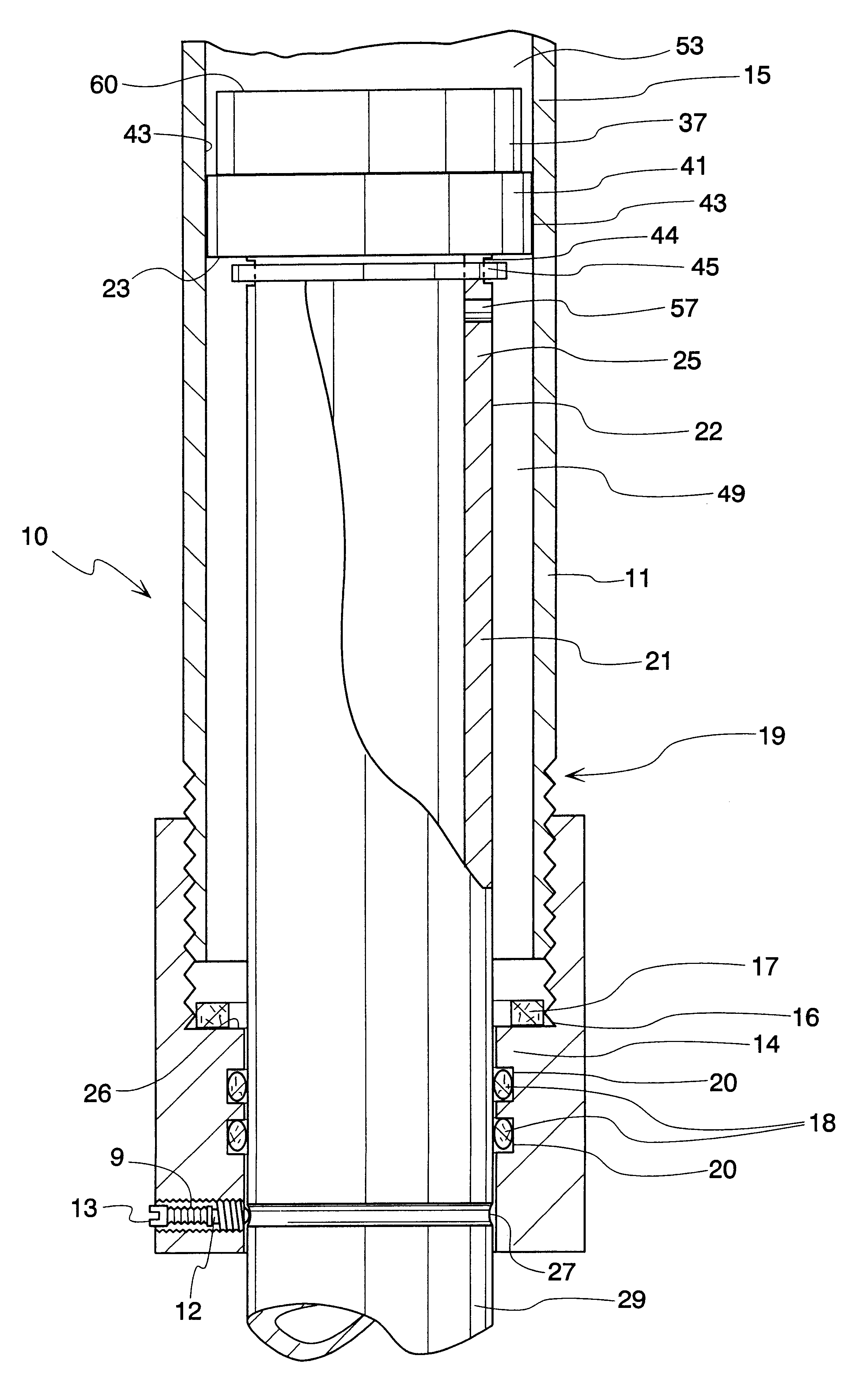
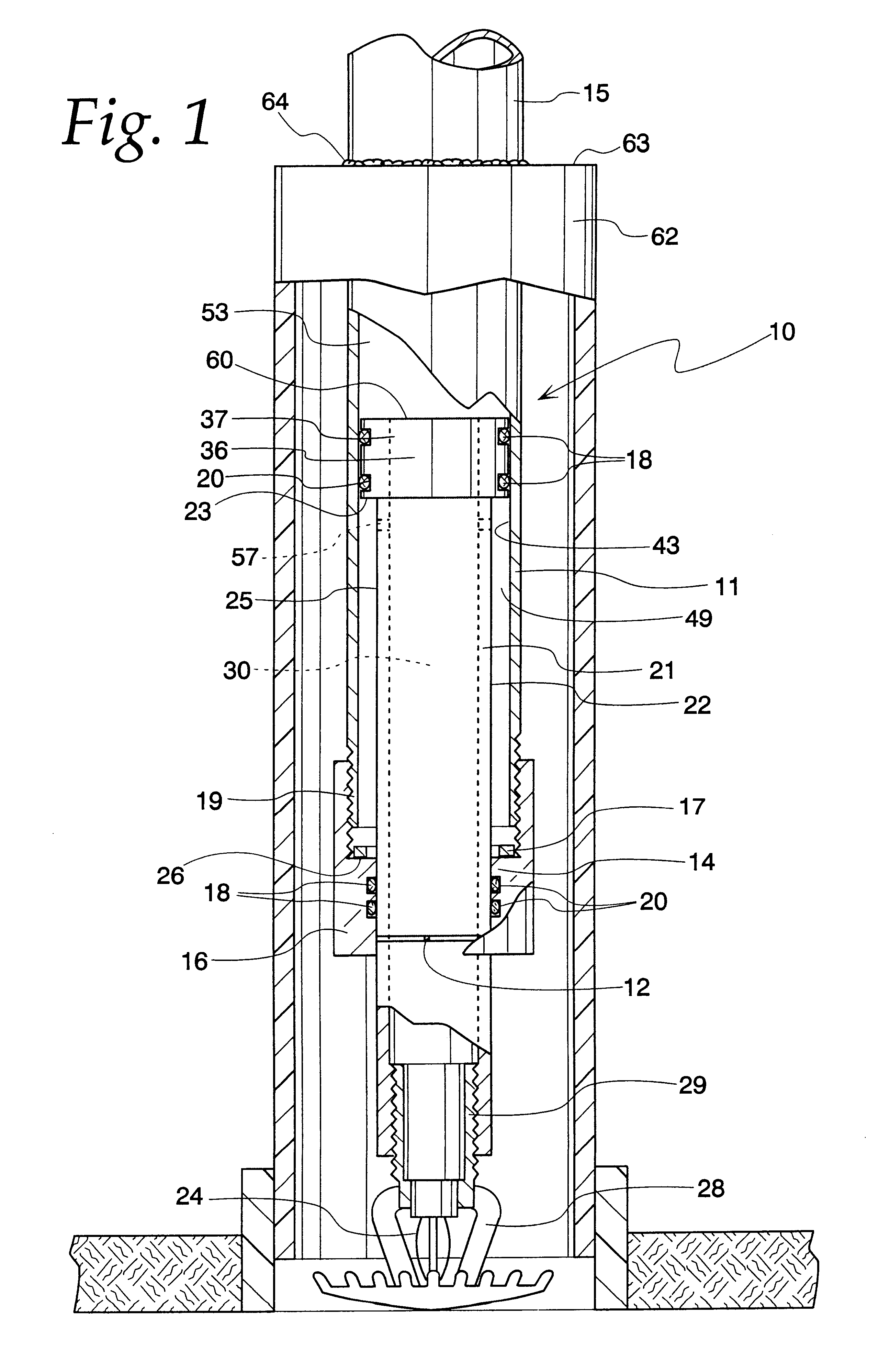
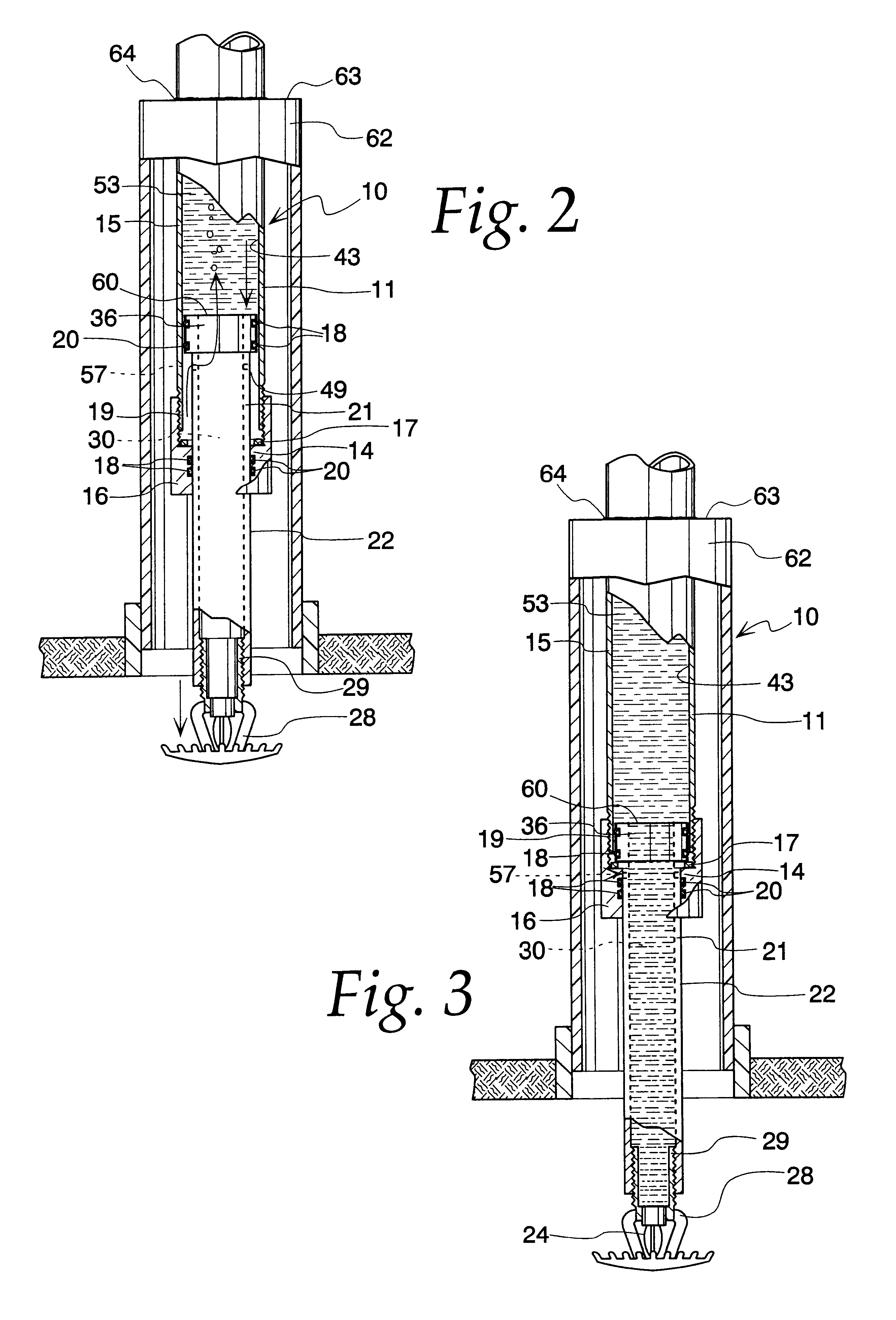
A principal object of the present invention is to provide a telescopic high pressure sprinkler system wherein the velocity of deployment of the sprinkler heads, each of which is attached to a piston nested in a cylinder, is regulated. A feature of the present invention is a plurality of gaskets or seals in sliding contact with the inner wall of the cylinder. An advantage of the present invention is that an air pocket, defined by positions of opposing gaskets serves to dampen deployment speeds of the sprinkler head as the pocket is longitudinally shortened.
In brief, the objects and advantages of the present invention are achieved by providing a device for deploying sprinkler heads in a telescopic sprinkler system comprising a plurality of gaskets and a chamber containing fluid for dampening the speed of deployment of the sprinkler heads.

Problems solved by technology

High velocity piston / stop impacts cause the telescopic system to suffer considerable damage after only a small number of tests.
Such slamming causes water to leak into the room.
This leads to flooding and further damage in instances where the piston strikes an object.
However, most damage is internal or otherwise undetected unless the telescopic system is taken apart after a test.
Thus, tests of a telescopic sprinkling system provide inadequate assurance that the system will deploy properly in case of an actual fire.
Damage incurred by the telescopic system cannot be obviated by reducing the pressure of the fluid injected in the distribution network.
Finally, when the telescopic systems are not deployed frequently, there is considerable static friction impeding the deployment of the systems, and again high pressure is required to overcome this friction.
The placement of adjustable fluid evacuation means on the cylinder wall of the device (as depicted in FIG. 5) may not necessitate flush mounting of the adjustable device.

Method used


Image

  • Device for regulating speed of deployment of sprinkler heads in preactive sprinkler systems
  • Device for regulating speed of deployment of sprinkler heads in preactive sprinkler systems
  • Device for regulating speed of deployment of sprinkler heads in preactive sprinkler systems

Examples


Embodiment Construction

An exemplary embodiment of the device has been constructed from ordinary materials to illustrate the utility of the invention in radio frequency-shielded environments. In this example, 1 1 / 2" schedule 40 black pipe was utilized as the outer conduit 11 or piston cylinder. The first end 15 of the outer conduit 11 is ideally suited to extend through magnetic field or RF-shielded channels 62 to attach to a water supply network. As depicted in FIGS. 1-3, the channels 62 may be outfitted with a cap plate 63, whereby the cap plate 63 forms an aperture to receive the outer conduit 11. The cap plate may be attached to the outer conduit 11 via welds 64.

The second end 19 or depending end of the outer conduit 11 slidably received an inner conduit or piston 21, which was fabricated from 1 inch stainless steel pipe, schedule 80.As depicted in FIGS. 1-3, the first end 25 of the piston 21 was adapted to receive a 1" NPS.times.3 / 4" machined part 36, to serve as the integrally molded piston-attached ...


PUM


Abstract

A telescopic high pressure sprinkler system is provided with a plurality of gaskets forming sliding seals between the piston and the outer conduit. Thus, the volume between the piston and the outer conduit forms a fluid chamber that is compressed as the piston is deployed so as to dampen the acceleration of sprinkler deployment. Furthermore, adjustable bleeder holes are provided to regulate the fluid chamber's compression while the gaskets provide a cushion when the piston comes to a stop. These bleeder holes also allow refilling of the piston fluid chamber.

Description

1. Field of the InventionThis invention relates to sprinkler systems and more specifically this invention relates to preaction telescopic automatic fire sprinkler systems in residential, commercial, and industrial buildings where the telescopic sprinkler assemblies are deployed repeatedly.2. Background of the InventionAutomatic fire extinguisher sprinkler systems have become an integral part of modern residential, commercial, and industrial buildings. Automatic sprinkler systems also are used in agriculture and in several manufacturing processes. Commonly these systems include a network of pipes for distributing fluid (hereinafter designated as the "spray fluid") to a plurality of sprinkler heads. Often, the spray fluid is injected at high pressure in the pipe network only after a command therefor has been generated, either automatically, for instance by a heat sensor for a fire-extinguishing system, or manually by an operator.There are several applications where the sprinkler heads...

Claims


Application Information

Patent Timeline
IPC IPC(8): A62C37/08A62C37/09
CPCA62C37/09
Inventor BONFIELD, DOUGLAS A.ZIELINSKI, STANLEY J.
Owner LINDGREN R F ENCLOSURES
Learn More