
Medical lead positioning and anchoring system

Inactive Publication Date: 2001-04-03
MEDTRONIC INC
View PDF8 Cites 232 Cited by
  • Summary
  • Abstract
  • Description
  • Claims
  • Application Information

AI Technical Summary

Benefits of technology

The present invention preferably comprises an apparatus fixing a lead at a cranial burr hole. One significant feature of the invention anchors the lead before the placement of a cap over the burr hole, thereby reducing the possibility of lead movement. This feature can be implanted directly into a cranium burr hole or it can be installed into a standard burr hole ring which is then implanted into the burr hole. A second significant feature of the present invention functionally locates the lead within a standard burr hole ring, thereby improving the location of the lead at the targeted stimulation area and reducing the possibility of injury to the brain.
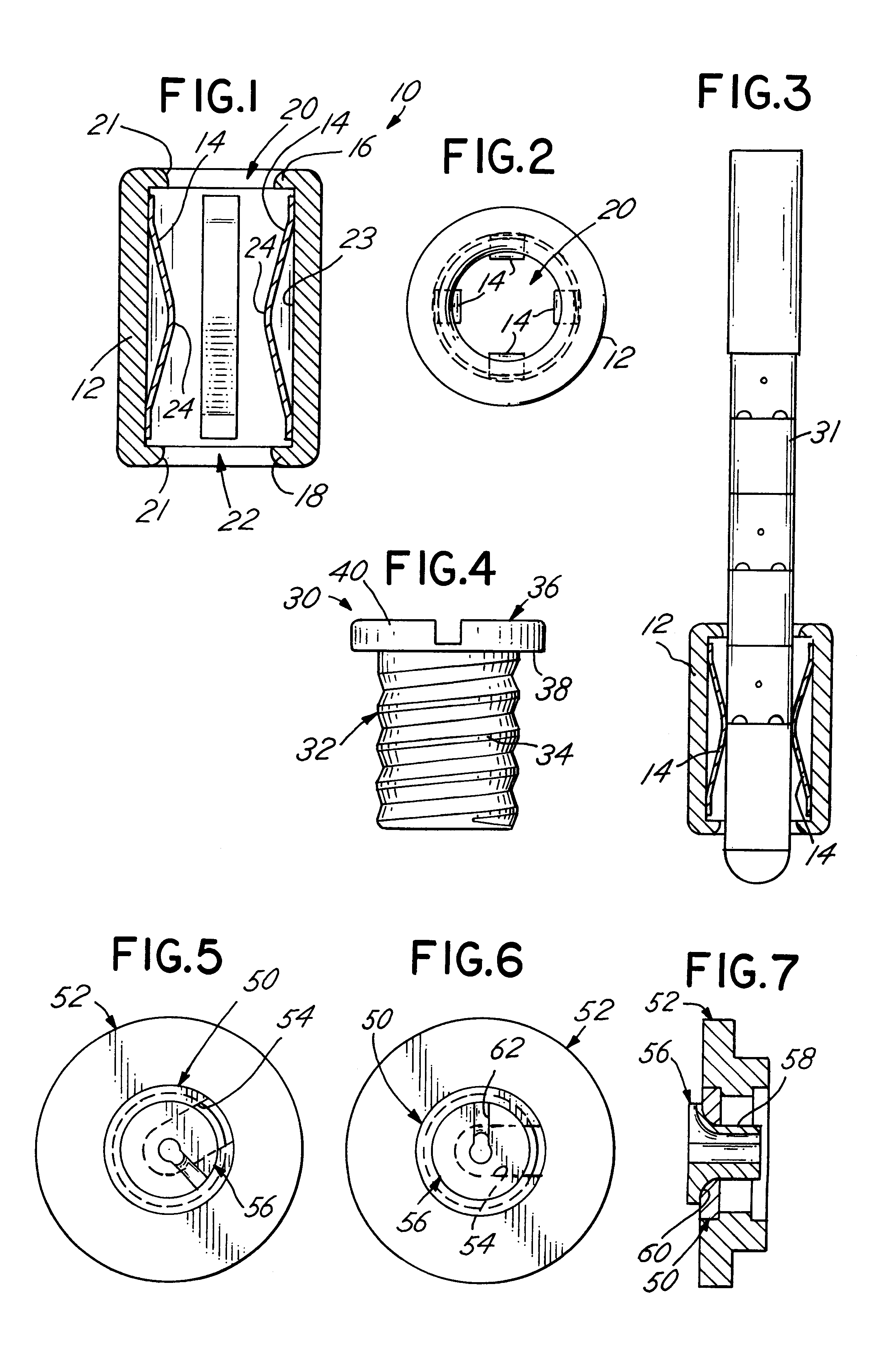
Another embodiment of the present invention comprises generally a rotatable disk having a slot. Received within the rotatable disk is a sleeve defining a second slot for capturing and fixing the lead relative to the rotatable disk. The previously identified sleeve and spring assembly may also be mounted in the rotatable disk. Significantly, the rotatable disk permits the implanted lead to be positioned at any location within the burr hole ring and thus anywhere within the burr hole. This functional positioning of the lead within the burr hole compensates for any offset between the burr hole and the desired projection path of the lead. Consequently, with these preferred embodiments, the lead may be located and maintained in a fixed position relative to the brain to allow electrical stimulation and / or drug infusion to the targeted area with improved precision and accuracy.

Problems solved by technology

Even one millimeter of travel of a properly positioned stimulation device may cause unsatisfactory results or, in some cases, severe injury to the brain.
The lead is thus susceptible to inadvertent movement by the physician during the cap installation period.
Further, during the interaction of the cap and ring, the lip of the cap tends to pull on the lead dislodging the lead from the targeted stimulation area.
Problems occur if the burr hole is not centered on the desired projection path of the lead.
The load on the lead body tip may force the electrodes away from the targeted stimulation area or it may place an undesirable amount of pressure on the brain.

Method used


Image

  • Medical lead positioning and anchoring system
  • Medical lead positioning and anchoring system

Examples


Embodiment Construction

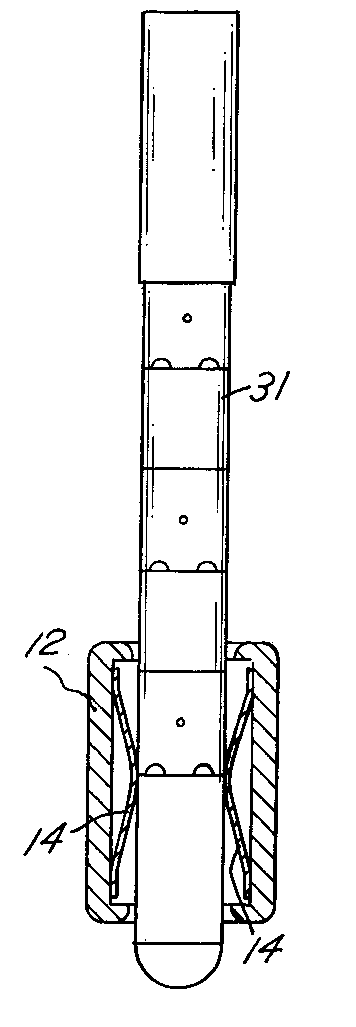
Referring to FIGS. 1-3, a preferred medical lead and catheter fixation device is depicted. The preferred lead fixation device 10 may be used in conjunction with a standard cranial burr ring or as a stand-alone device implanted in a cranial burr hole. Whether or not a separate burr ring is used with a particular patient will depend on the specific circumstances involved in that patient's case. In addition, the lead fixation device 10 may also be used with the rotatable disc 50, described more fully below, which is mounted to a standard burr hole ring.

The lead fixation device 10 of the present invention defines a sleeve 12, preferably cylindrical in shape, and a lead-interactive member, preferably a plurality of springs 14. The lead fixation device 10 is designed to fit within a conventional burr hole ring, or the burr hole ring 52 more fully discussed below, which is then implanted in the cranium. A lead, or cannula if used, is then inserted into the lead fixation device 10. The lead...


PUM


Abstract

There is disclosed a medical apparatus for positioning and anchoring a lead to a cranium burr hole. The apparatus comprises generally a sleeve and a plurality of springs positioned within the sleeve. The apparatus may be inserted within a conventional burr hole ring or serve as a stand-alone anchoring device that fits within a burr hole. Once a lead is inserted into the sleeve between the plurality of springs, the springs exert a radial force on the lead body, thereby holding the lead in the desired position. The apparatus may also include a circular disc, defining a slot, mountable within the burr hole ring. The circular disc permits the selective positioning of the lead within the burr hole.

Description

BACKGROUND OF THE INVENTION1. Field of the InventionThe present invention relates to an apparatus for securing implanted medical devices and more particularly to an apparatus for securing implanted medical devices such as electrical stimulation leads or catheters, or a combination thereof, within a cranial burr hole and for varying the functional location of the leads or catheters within the burr hole.2. Description of the Related ArtMedical procedures involving access to the brain through a burr hole in the skull are under increasing use. Two such procedures are electrical stimulation of the brain for such purposes as relief of chronic pain and treatment of movement disorders, and the use of parenchymal catheters for infusing pharmaceutical agents. A typical electrical brain stimulation system comprises generally a pulse generator operatively connected to the brain by a lead having at its distal end at least one electrode designed to be implanted within the brain, and having at its...

Claims


Application Information

Patent Timeline
IPC IPC(8): A61N1/05
CPCA61B5/6864A61N1/0539
Inventor BAUDINO, MICHAEL D.CROSS, JR., THOMAS E.
Owner MEDTRONIC INC
Learn More