
Method, apparatus, and program for printing using modified print attributes

a technology of print attributes and print attributes, applied in the field of impact printers, can solve the problems of increased power consumption, high print pressure setting of all types of media, and increased power consumption

Inactive Publication Date: 2001-03-20
IBM CORP
View PDF17 Cites 65 Cited by
  • Summary
  • Abstract
  • Description
  • Claims
  • Application Information

AI Technical Summary

Problems solved by technology

A drawback of conventional printers is that after the print condition specifying the high print pressure is set, all types of media are printed with the high print pressure settings.
Furthermore, if the print operation using the high print pressure is continuously used on the thin print medium, several problems are likely to occur.
The high print pressure requires increased power consumption as compared to a lower print pressure resulting in a temperature increase of the print head.
To minimize the increase in temperature, a print operation is frequently suspended which often lowers the performance of a print operation.
Additionally, the cost is increased due to the use of a cooling fan.
Also, the high temperature often causes erroneous operations in the circuit cards and damages the print head.
Additionally, the life time of a print ribbon is shortened by high print pressure when the ink ribbon fiber is weakened as a result of ink loss in an early stage.
As a result of the weakened fiber in the ink ribbon, the elasticity of the ink ribbon is lost.
This may cause the ink ribbon to catch a wire in the print head resulting in a jam.
The high print pressure reduces the life time of the print head by increasing the wear of print wires at its ends and core.
The high print pressure often damages the surface of a platen.
If a print operation using high print pressure is used on the thin print paper, a dent is likely to be formed on the surface of the platen due to the impact force of the print wires.
This may cause the print paper to jam by catching the ink ribbon on the print wire leading to the deterioration of print quality and the breaking of the print wires.
Furthermore, when using a movable platen mechanism going up and down, the platen should have the proper weight thereby limiting the material used for the platen.
This may be a significant problem for this type of printer.
Another disadvantage of using high print pressure on thin print paper is the loud sound produced which may be noisy for the operator.
A print operation using high print pressure often damages thin paper by making holes in the thin paper.
If the pressure force is increased too much, it may cause the carbon papers or the pressure sensitive papers to generate color.
Thus, the pressure force is often limited by the number of sheets of the passbook and printing the characters at a location which does not overlap with the air layer.
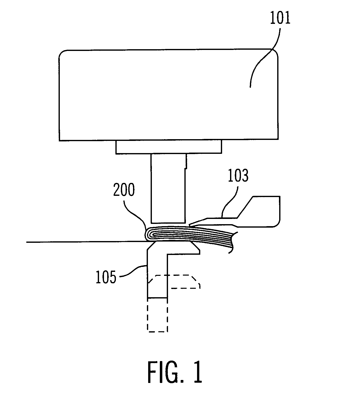
A folding portion of a vertical type passbook shown in FIG. 3 also causes the same type problem as that in the lateral type passbook.
This problem cannot be solved by the mechanism of the platen and the bar back.
However, a printer using this scheme has the following drawbacks due to the fact that it is designed to simultaneously print two types of print papers.
In other words, it is impossible to print the two types of print paper at the high print pressure or normal print pressure.
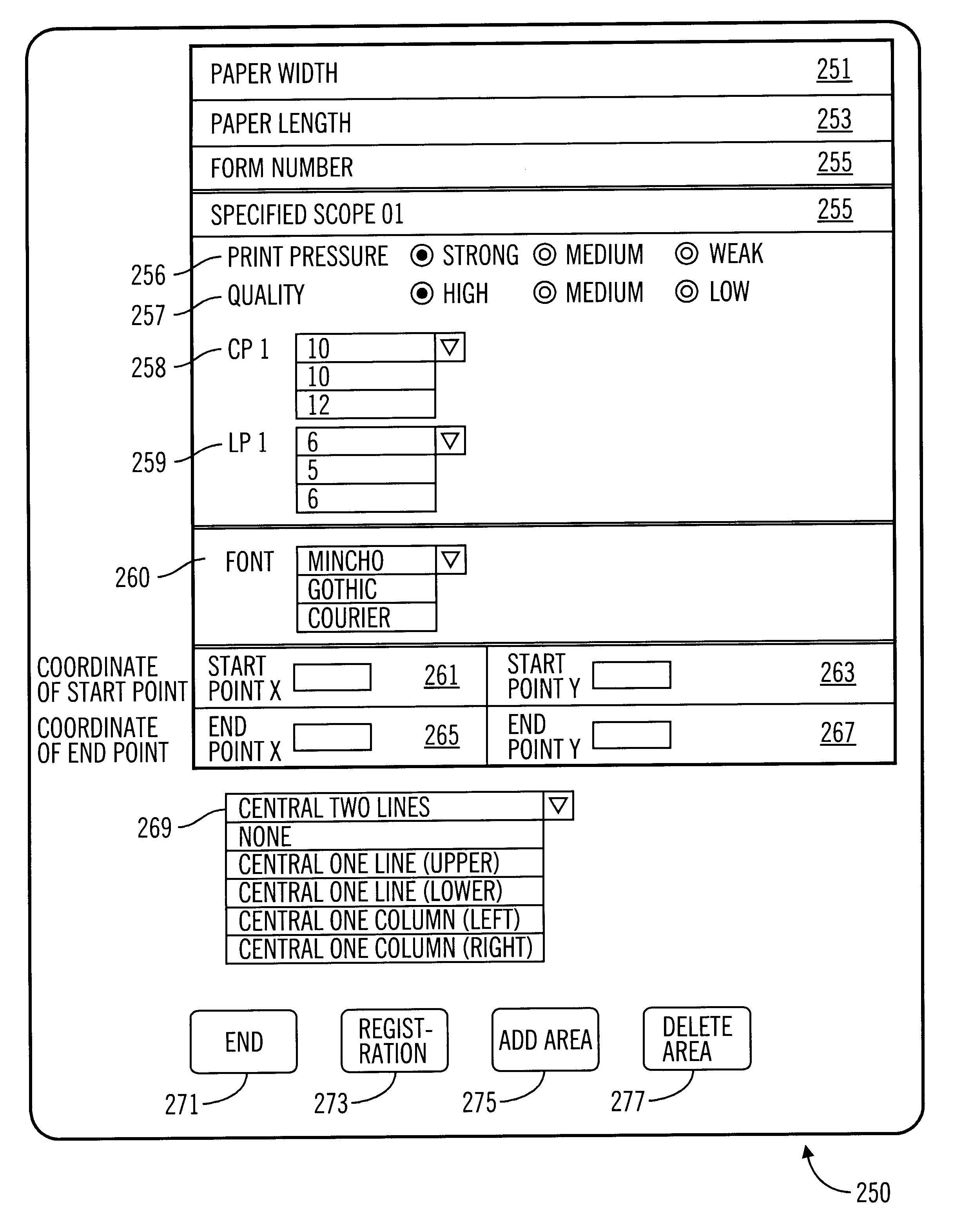
(3) It is impossible to specify a particular print area, such as one character or one particular line, which requires the high print pressure.
(4) Types of print papers to be printed at the high print pressure are limited since the position for sensing the print paper is fixed.
(1) It is difficult to determine whether the current print paper requires the high print pressure, or not. That is, this scheme is effective only when media requiring high print pressure are continuously fed.
(2) In the case where print papers having different sizes require high print pressure, the scope requiring the high print pressure is not specified for each paper size.
(3) To set the scope requiring the high print pressure, it is necessary to input the coordinate values via a keyboard. The scope can not be automatically set by insertion of the print paper to the printer.
In this scheme, however, the same problems associated with PUPA 61-217257 apply because the print operation of a validation print paper and a journal print paper is performed on the same print line.
Conventional printers also have drawbacks associated with the high quality print operations.
The reduction of the dot density apparently degrades the print quality.
In the case where high print quality is required for only a particular portion, such as a particular line(s) or a particular column(s), conventional printers require the whole page to be printed in a high quality print mode, due to the fact that this printer can not specify the particular portion to be printed in the high print mode.

Method used


Image

  • Method, apparatus, and program for printing using modified print attributes
  • Method, apparatus, and program for printing using modified print attributes
  • Method, apparatus, and program for printing using modified print attributes

Examples


Embodiment Construction

A. System Configuration

FIG. 1 illustrates a printer 100 with a medium 200 inserted according to one embodiment of the present invention. FIG. 5 illustrates a block diagram of the electronic components of the printer 100.

With respect to FIG. 5, CPU 145 is electrically coupled to various sensors 121, 123, 125, 127, 129, and 141, a drive circuit 161, an operator panel 143, and various memory devices 147, 149, and 167. The CPU 145 receives signals from the various sensors to control drive circuit 161 in accordance with a control program stored in the various memory devices. For one embodiment of the present invention, the CPU 145 and / or drive circuit 161 may be referred to as a control circuit. The operator panel 143 is used for the user input and includes a display panel.

FIG. 4 illustrates components in the paper path of the printer. The media in sensor (i.e. an insertion entrance sensor) 121 detects the insertion of a medium 200, such as the paper, into printer 100. The top edge senso...


PUM


Abstract

The present invention provides a printer system responsive to the request of an operator for performing specified control on a specified portion of a medium during a print operation. Such control minimizes the labor required by an operator to change the set-up condition of the printer when different print media is used. Print operations having modified print attributes for specified areas are set-up for each type of media in advance and stored in a storage device of a printer or a host processor for controlling the printer, such as a personal computer or a server. When a medium is inserted into the printer, medium identifying information, such as a bar coded form number or the size of the medium is used to determine which record stored in the storage device corresponds to the selected medium. The controlled print operation, such as a high print pressure printing, a high quality printing, a change or modification of line / column space, or a modification of font, is made in the area specified by the position data.

Description

1. Field of the InventionThe present invention relates to impact printers, and more particularly, to a scheme for controlling print attributes in impact printers.2. Description of the Prior ArtVarious types of print media are often used by financial institutions when printing. Printing may be performed on a thin print medium such as a single sheet of paper, a thick print medium such as a pressure sensitive paper stack or a carbon paper stack including more than four sheets, or a passbook including multiple pages. In order to maintain the desired print quality when printing onto thick print media or passbooks including more than two pages, it is necessary to print them by setting the print pressure to a level which is higher than that used for thin print medium including one or two sheets.Conventional printers set the print pressure to an optimum print pressure (1) by using an expensive sensor which senses a thickness of the inserted print paper, (2) by using a lever which is selecti...

Claims


Application Information

Patent Timeline
IPC IPC(8): B41J3/28B41J11/00B41J21/16B41J2/30B41J21/00G06K7/00
CPCB41J3/28B41J3/283B41J11/0035B41J11/008B41J11/009
Inventor TAKENOSHITA, HIROYUKISAWA, TSUTOMU
Owner IBM CORP
Learn More