
Method and apparatus for forming image

a technology of forming apparatus and image, applied in printing and other directions, can solve the problems of not being accepted by commercial printing, no exclusive paper is available, and the ink jet printing system is not expensive, and achieves the effect of sacrificing the high degree of freedom of the ink jet printing system

Inactive Publication Date: 2005-05-26
CANON KK
View PDF24 Cites 74 Cited by
  • Summary
  • Abstract
  • Description
  • Claims
  • Application Information

AI Technical Summary

Benefits of technology

[0016] It is an object of the present invention to provide a method and an apparatus for forming an image which can form a high-quality image on a great variety of print media regardless of the surface roughness or ink absorptivity of the print medium, without sacrificing the high degree of freedom of the ink jet printing system.
[0019] applying a first material to a print medium, the first material increasing the rate of ink transferred from the intermediate transfer body to the print medium; and
[0029] applying a second liquid improving surface energy of the print medium to the print medium; and
[0041] an applying means for applying a first material to a print medium, the first material increasing the rate of ink transferred from the intermediate transfer body to the print medium; and
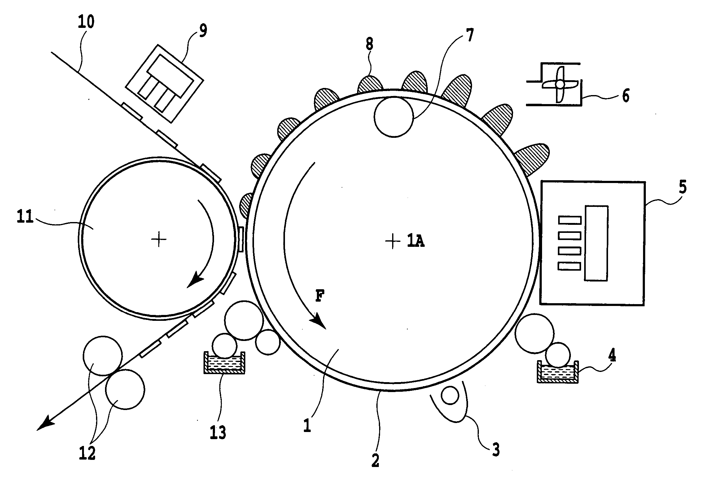
[0045] According to an embodiment of the present invention, inks are ejected to the intermediate transfer body to form an ink image. Then, the ink image is transferred to the print medium to which the ink transfer adjuvant has already been applied. This increases the surface energy of the print medium and improves its surface smoothness to provide different print media with uniform surface properties. It is thus possible to increase the transfer rate. Therefore, a high-quality image can be formed on a variety of print media.

Problems solved by technology

On the other hand, disadvantageously, an output image quality depends on print media (mainly paper) and exclusive print media must be used to output an image from a digital camera so that the image has a high quality.
Exclusive paper for high image quality outputs is expensive, and there are only a few types of such paper.
In particular, no exclusive paper is available such as thin glossy print paper suitably used for offset printing.
This is partly why the ink jet printing system is not accepted by commercial printing.
Accordingly, if only a little or no ink jet ink is absorbed into the print media, an enormously long time is required for drying.
If the ink jet ink contains a nonvolatile liquid, it may not appropriately dried.
Moreover, inappropriate printing may occur; adjacent printed ink droplets may be mixed together (bleeding) or an ink droplet having already impacted a print medium is drawn to an ink droplet impacting the print medium later (beading).
Thus, at present, it is very difficult to form images on print media into which a little or no ink jet ink is absorbed, using the ink jet printing system.
In contrast, if an image is printed on a print medium with an excessively high ink permeability, a coloring material strike-through may occur resulting in insufficient coloring or the surface of the print medium may become wavy.
Likewise, if a thin print medium is used, ink strike-through caused by penetration of inks or a wavy surface such as cockling may occur.
In this manner, printing by the ink jet printing system tends to be significantly limited by the amount of ink absorbed into the print medium.
However, an increase in the amount of ink applied increases the incidence of bleeding or beading, described above.
Moreover, in terms of productivity, it is not preferable to increase the amount of moisture removed or a load on cleaning of the transfer body, besides the amount of ink applied.
However, if a liquid layer that is the release layer is provided on the transfer body, an ink image formed on this layer is not fixed.
Consequently, the ink image may be “distorted” or “bled” or “misalignment” may be caused by a transfer pressure exerted during transfer.
This hinders the drying of the ink image, thus affecting an increase in speed and the robustness of the image.
However, defects may occur in this apparatus; a long time may be required to absorb the solvent, or absorption holes formed in the intermediate transfer body to absorb the solvent may be clogged up.
Accordingly, a large amount of energy is consumed in recovering the transfer body to its initial state, including the absorption of the solvent.
Thus, regardless of whether to use the method (direct printing) of forming an image by allowing the ink jet head to eject inks directly to a print medium or the transfer ink jet printing method, there remain problems to be solved in terms of the degree of freedom for available print media.
However, even for the system using the intermediate transfer body, there remain problems to be solved in order to transfer high-quality ink images to the print medium.
Accordingly, a high transfer rate cannot be achieved unless the transfer is carried out under the optimum transfer conditions.
However, it is difficult to control the transfer conditions in accordance with the ink absorptivity.
Therefore, it is difficult to achieve a high transfer rate taking the ink absorptivity into account.

Method used


Image

  • Method and apparatus for forming image
  • Method and apparatus for forming image
  • Method and apparatus for forming image

Examples


specific examples

[0137] Now, the present invention will be specifically described taking several examples by way of example. In the following description, the term “parts (pts)” or “%” means a weight basis unless otherwise specified.

example 1

[0138] The image printing system according to the present invention will be described below step by step.

(a) Formation of an Ink Image on the Intermediate Transfer Body

[0139] In the present example, as an intermediate transfer body, a drum was used which was made of aluminum and to which commercially available NBR having a rubber hardness of 80° and a thickness of 0.2 mm was glued. An ink jet printing apparatus (a nozzle density of 600 dpi, an ejection amount of 4 pl, and a driving frequency of 5 kHz) and an ink having a composition shown below was used to form a mirrored image of a character on the intermediate transfer body.

CI. food black 2: 2.5 partsGlycerin:  5 partsDiethylene glycol:  7 partsSurface active agent:  1 part(acetylenol EH manufactured byKawaken Fine Chemicals Co., Ltd.)Ion-exchanged water:84.5 parts

(b) Application of the Ink Transfer Adjuvant to the Print Medium

[0140] On the other hand, an ultrasonic spray coating device was used to coat 2.5 ml / m2 of pure wa...

example 2

(a) Formation of an Ink Image on the Intermediate Transfer Body

[0142] In the present example, a drum was used which was made of aluminum and on which silicone rubber (KE30 manufactured by Shin-Etsu Chemical Co., Ltd.) having a rubber hardness of 60° was coated to a thickness of 0.5 mm. Then, a roll coater was used to coat a fluorine-containing surface active agent (Surfron S-141 manufactured by SEIMI CHEMICAL Co., Ltd.) on the surface of the intermediate transfer body.

[0143] Then, the roll coater was used to coat a 5 wt % water solution of polymer flocculant (C577S manufactured by Mitsui Sitech Co., Ltd.).

[0144] Then, an ink jet printing apparatus (a nozzle density of 1,200 dpi, an ejection amount of 4 pl, and a driving frequency of 8 kHz) was used to form a mirrored color image. Inks were used which had compositions shown below.

Dyes shown belowBlack:CI. food black 2Cyan:CI. direct blue 199Magenta:CI. acid red 289Yellow:CI. acid yellow 23Glycerin:10 partsDiethylene glycol: 5 p...


PUM


Abstract

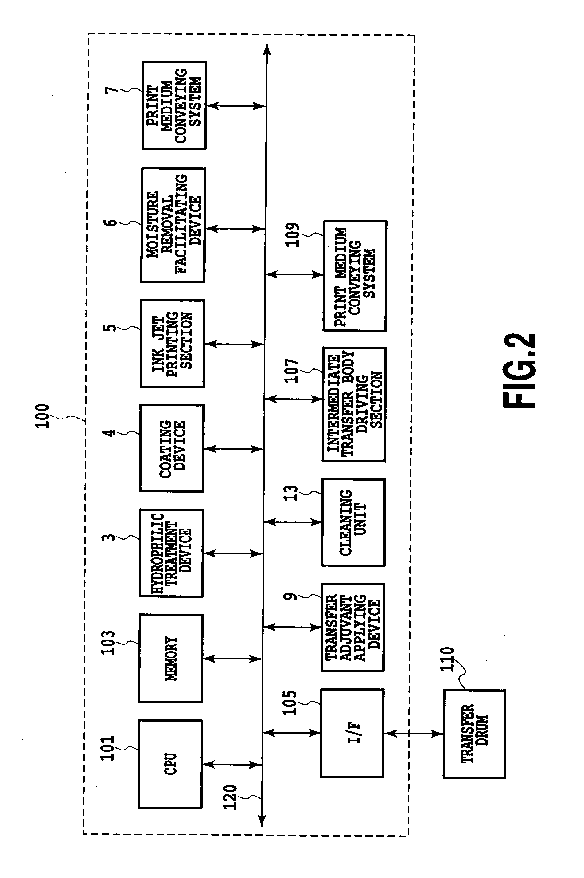
A method and apparatus for forming an image which can form a high-quality image on a great variety of print media regardless of the surface roughness or ink absorptivity of the print medium, without sacrificing the high degree of freedom of the ink jet printing system are provided. An ink jet printing section ejects ink to an intermediate transfer body to form an ink image on the intermediate transfer body. Before the ink image thus obtained is transferred to a print medium, an ink transfer adjuvant is applied to the print medium. Then, the ink image formed on the intermediate transfer body is transferred to the print medium to which the ink transfer adjuvant has been applied.

Description

BACKGROUND OF THE INVENTION [0001] 1. Field of the Invention [0002] The present invention relates to a method and an apparatus for forming an image, and more specifically, to a method and an apparatus for forming an image in which an intermediate transfer body used to form an image on a print medium in order to avoid adverse effects on the amount of ink absorbed by the print medium. [0003] 2. Description of the Related Art [0004] At present, as a method of forming an image using an ink jet printing system, output devices of personal computers and the like mainly employ a direct printing system that forms an image by ejecting ink directly on a recording medium. The direct printing system has a simple apparatus configuration. Further, relatively inexpensive relevant products are commercially available on the market. Accordingly, this system is suitable used as a simple printer. On the other hand, disadvantageously, an output image quality depends on print media (mainly paper) and excl...

Claims


Application Information

Patent Timeline
IPC IPC(8): B41J2/01B41J2/005
CPCB41J2/0057
Inventor TANIUCHI, HIROSHIMOURI, AKIHIRO
Owner CANON KK
Learn More