
Intraocular lens with accommodative properties

a technology of ocular lenses and ocular lenses, applied in intraocular lenses, eye implants, medical science, etc., can solve the problems of inability to continuously adjust the focusing range in vivo, the natural ability of human lenses to change their shape and therefore refractive power, and the gradual loss of age-related ability to adjust the refractive power of all cited prior art artificial lenses

Inactive Publication Date: 2001-03-13
TASSIGNON MARIE JOSE B
View PDF9 Cites 232 Cited by
  • Summary
  • Abstract
  • Description
  • Claims
  • Application Information

AI Technical Summary

Benefits of technology

The primary purpose of the new lens design and method of implantation is therefore to make use of all the natural mechanisms involved in the accommodative reflex: the change in pupil diameter of the eye and the changes in state of contraction of the ciliary muscle, in order to assist in focusing of nearby objects.
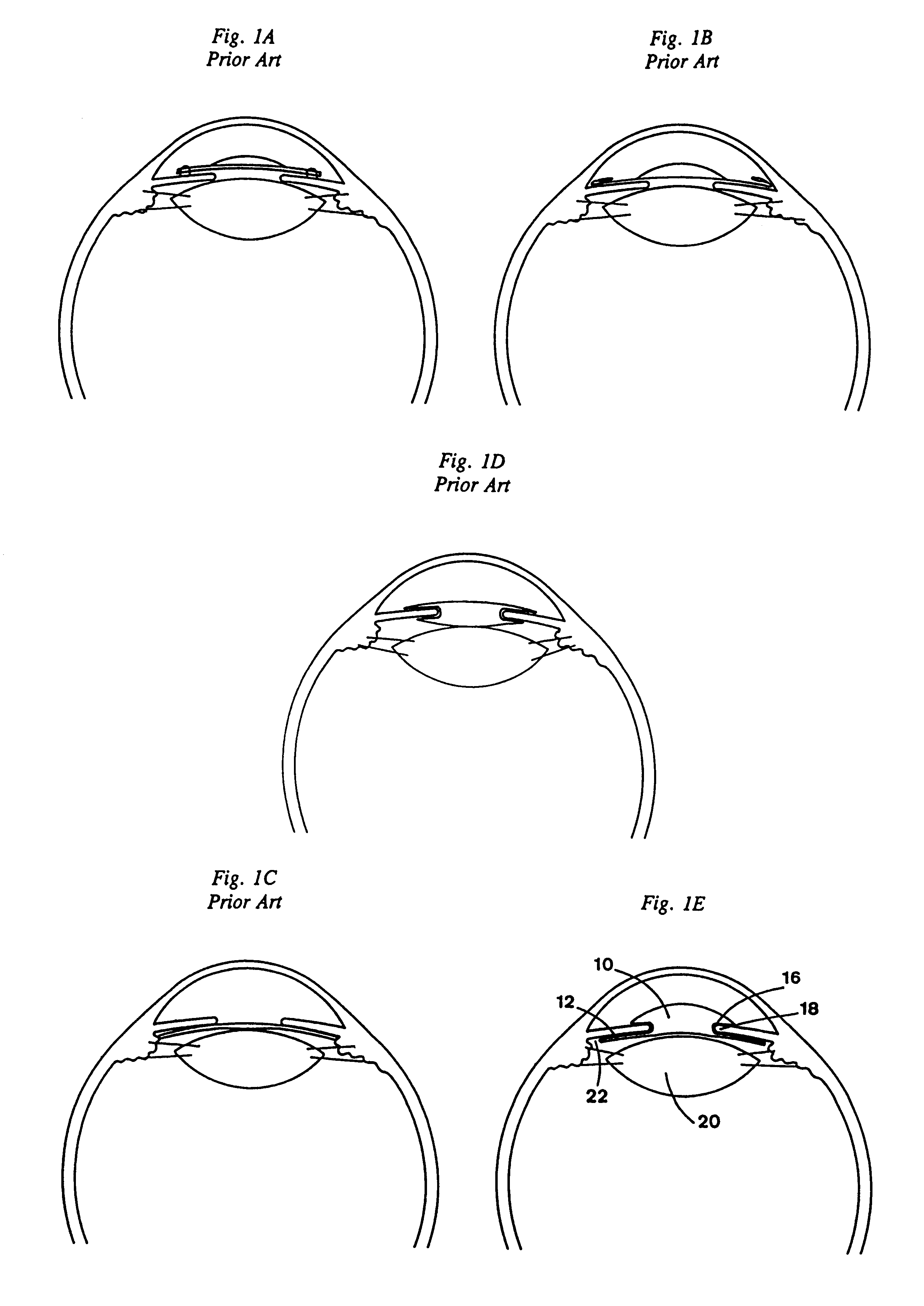
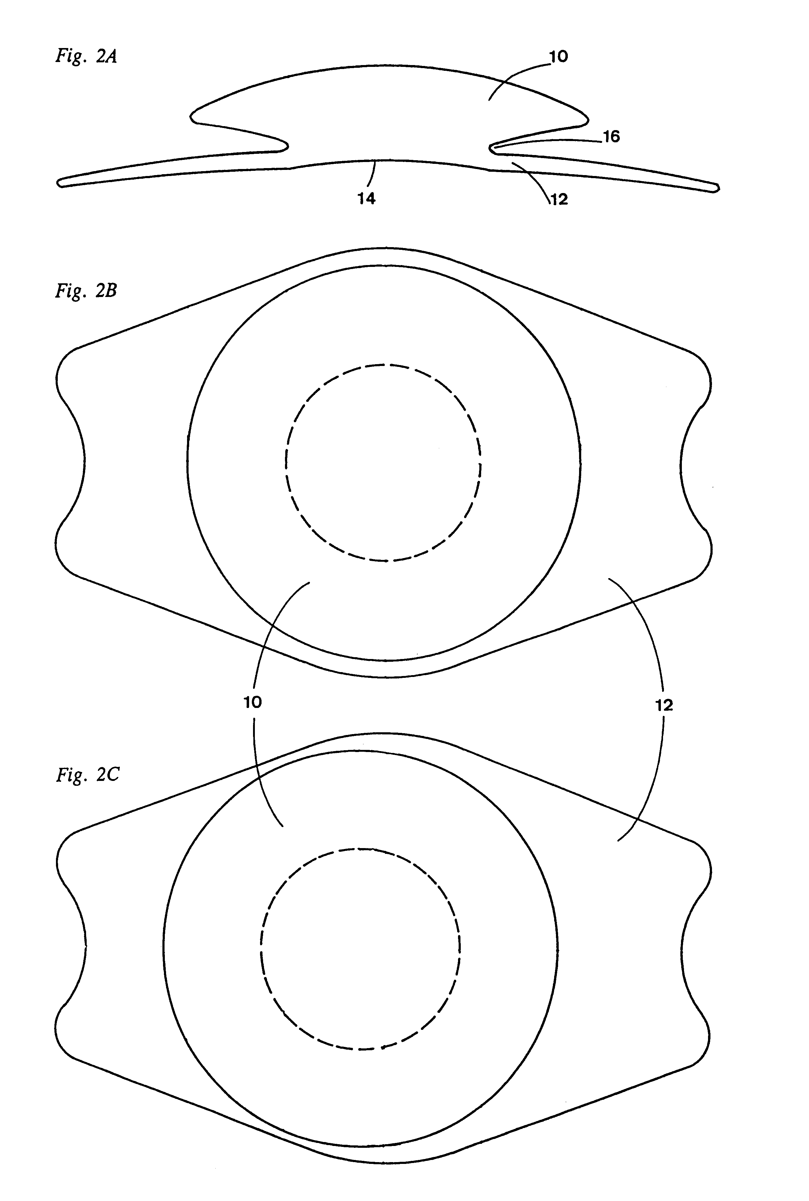
In summary, the new intraocular lens consists of two parts. The posterior part or haptic part is to be inserted behind the iris and in front of the natural lens or artificial implant. The overall length and structure of this part is variable and should fit as close as possible into the ciliary sulcus for two reasons. First, to be able to respond to changes in the state of contraction of the ciliary body and second, to prevent excessive lateral movement and luxation of the lens. An anterior or optical part, made of flexible material, is placed before the iris. Its diameter is variable but should be large enough to cover the pupillary margins to some degree under various conditions of natural dilation. This is important for optical reasons as well as mechanical reasons, to avoid luxation of the optical part behind the iris. The anterior and posterior part of the lens are separated by a compressible circular groove in which the iris will settle. The diameter of this groove is important and must be slightly larger than the pupillary diameter measured under normal photopic daylight conditions and for distance vision. Since the pupil becomes smaller in near vision, the iris will exert a slight pressure at the level of the groove of the lens which will cause a progressive and evenly distributed flexing of the anterior part of the intraocular lens, as the diameter of the compressible circular groove slightly decreases. This flexing will induce an increase in refractive power which basically corresponds to a variable part of the amount necessary for focusing nearby objects.
The use of the change in pupil diameter versus other methods, mentioned in the prior art, is advantageous for several reasons. First, it is easy to observe dynarnically, before the intervention, the change of the pupil diameter under various conditions of background illumination and distances of focusing. Second, during the operation, the intervention is under maximal visual control of the surgeon since no critical steps of the intervention have to take place behind the iris. Lastly, the post-operative status and functioning of the implant is easily observed using the biomicroscope.
Furthermore, this new lens design will avoid the disadvantages of the anterior chamber angle fixation phakic lenses. Because no parts of the new lens will touch the anterior chamber angle, secondary glaucoma and pain will not occur. Because this new lens is located at a safe distance from the corneal endothelium and has no chance to luxate anteriorly because of its attachment to the posterior part of the lens, there is no risk for endothelial touch and subsequent endothelial cell loss. Because this new lens respects the shape and the centration or decentration of the pupillary border, no pupillary deformation will occur.
Also, this new lens design will avoid the disadvantages of the iris fixated anterior chamber phakic lenses. Because this new lens design has no fixed iris fixation but a groove which accommodates the iris in a flexible way, no iris perforation nor pupillary deformation can occur. Because this new lens is covering completely the pupillary margins, no complaints of halos due to decentration are to be expected. Because of its large distance from the corneal endothelium, no corneal touch is possible.
At last, this new lens design will avoid the disadvantages of posterior chamber phakic lenses that solely rely on stabilization by the ciliary body. Because the lens has primarily an iris suspension and streamlined design, lenticular touch and irritation of the ciliary body will be minimized.

Problems solved by technology

Continuous adjustment of focusing range in vivo is not possible.
In presbyopia, the natural capability of the human lens to change its shape and therefore refractive power, is gradually lost with age.
All of the cited prior art artificial lenses however cannot change shape to adjust refractive power on a continuous basis and some may suffer from multiple image formation or blur because of the different active optical areas of the lens that are needed to focus at different distances.
This accommodative process fails when the natural lens stiffens with age or is replaced with an artificial lens.
However, these lenses seem to have very little or no accomodative effect.
None of the aforementioned lenses can accommodate or change shape, based on a change in diameter of the pupil during the process of accommodative focusing of the eye.
Because of its large distance from the corneal endothelium, no corneal touch is possible.

Method used


Image

  • Intraocular lens with accommodative properties
  • Intraocular lens with accommodative properties
  • Intraocular lens with accommodative properties

Examples


Embodiment Construction

FIGS. 1A, 1B, 1C and 1E illustrate the differences in positioning of the new lens in the eye versus the cited prior art. With the new lens design, the anterior optical part is placed before the iris, the pupil margin that contains the sphincter muscle of the iris is inserted in the circular and compressible groove, and the posterior haptic part is placed behind the iris and before the natural lens in the sulcus delineated by the ciliary body and iris. This new streamlined lens design, according to FIG. 1E, permits a more physiologic centration within the pupil and offers the advantages previously mentioned.

The preferred embodiment of the optical part 10 of the intraocular lens is circular and its anterior surface is convex, although other configurations and shapes may be employed. The optical part 10 of the intraocular lens may be constructed of any of the currently used deformable substances such as silicone polymeric materials, acrylic polymeric materials, hydrogel forming polymer...


PUM


Abstract

A new lens design and method of implantation uses the change in pupil diameter of the eye concurrent with the changes induced by a contraction of the ciliary muscle during the accommodative reflex, in order to assist in focusing of nearby objects. This new intraocular lens consists of two parts. The posterior part or haptic part is inserted behind the iris and in front of the natural lens or artificial implant. Its main purpose is to participate in the accommodative mechanism and to prevent excessive lateral movement and luxation of the lens. An anterior or optical part is made of flexible material and is placed before the iris. Its diameter is variable but should be large enough to cover the pupillary margins to some degree under various conditions of natural dilation. The anterior and posterior part of the lens are separated by a compressible circular groove in which the iris will settle. The diameter of this groove is slightly larger than the pupillary diameter measured under normal photopic daylight conditions and for distance vision. Since the pupil becomes smaller in near vision, the iris will exert a slight pressure at the level of the groove of the lens which will cause a progressive and evenly distributed flexing of the anterior part of the intraocular lens, as the diameter of the compressible circular groove slightly decreases. This flexing will induce an increase in refractive power which corresponds to a variable part of the amount necessary for focusing nearby objects.

Description

BACKGROUND--FIELD OF INVENTIONThis invention relates to intraocular lenses for implantation in the human eye, in particular intraocular lenses having in vivo accommodative properties to assist or replace part of the focusing capabilities of the eye.BACKGROUND--DESCRIPTION OF PRIOR ARTThe insertion of an intraocular lens in the human eye to correct a refractive error is a well-known surgical procedure. In this procedure, the natural lens may or may not be removed. Several types of intraocular lenses are currently available for this purpose. It is possible to change the optical properties of some of these lenses in vivo, as exemplified in U.S. Pat. No. 5,728,155 awarded to Anello et al. and U.S. Pat. No. 5,725,575 awarded to O'Donnell. These lenses allow a one-time adjustment or finetuning of focusing properties after implantation. Continuous adjustment of focusing range in vivo is not possible. Of particular interest are lenses placed in the anterior chamber of the eye for the correc...

Claims


Application Information

Patent Timeline
IPC IPC(8): A61F2/16
CPCA61F2/1602A61F2/1635A61F2002/1605A61F2/1605
Inventor TASSIGNON, MARIE-JOSE B.
Owner TASSIGNON MARIE JOSE B
Learn More