
Video encoding apparatus and video decoding apparatus

a technology of video encoding and video decoding, which is applied in the direction of color television with bandwidth reduction, television systems, instruments, etc., can solve the problems of encoding efficiency reduction and number of encoded

Inactive Publication Date: 2001-03-06
KK TOSHIBA
View PDF8 Cites 30 Cited by
  • Summary
  • Abstract
  • Description
  • Claims
  • Application Information

AI Technical Summary

Benefits of technology

It is an object of the present invention to provide a video encoding apparatus and video decoding apparatus, which can efficiently encode and decode alpha-map information as subsidiary video information that express the shape of the object and its position in a frame.
The apparatus with the above arrangement is characterized in that a plurality of types of variable-length coding tables are prepared, and these variable-length coding tables are switched in correspondence with the pattern of the already encoded alpha-map, in encoding / decoding that reduces the number of encoded bits by encoding the symbol that specifies the position of a change pixel using the variable-length coding table. According to the present invention mentioned above, an effect of further reducing the number of encoded bits of the alpha-map can be obtained.
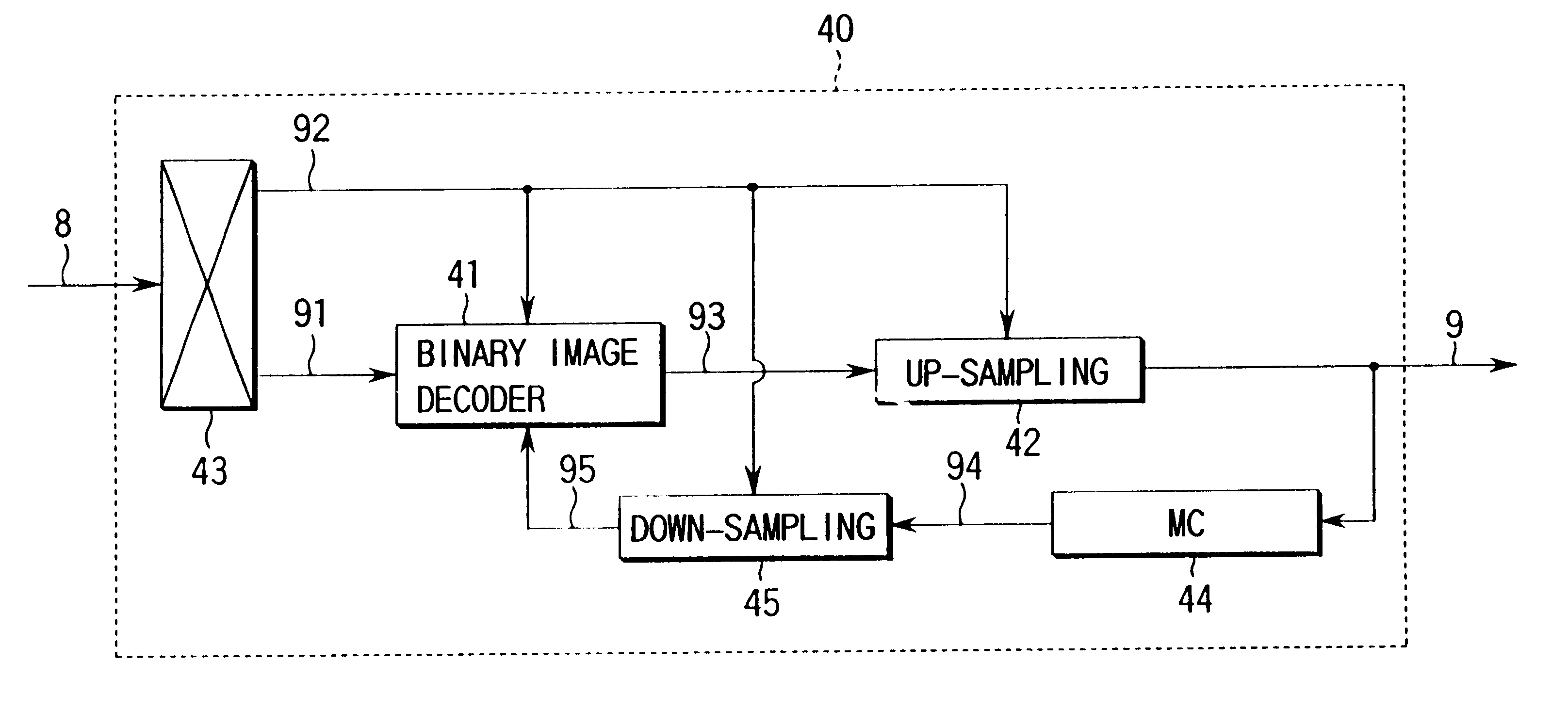
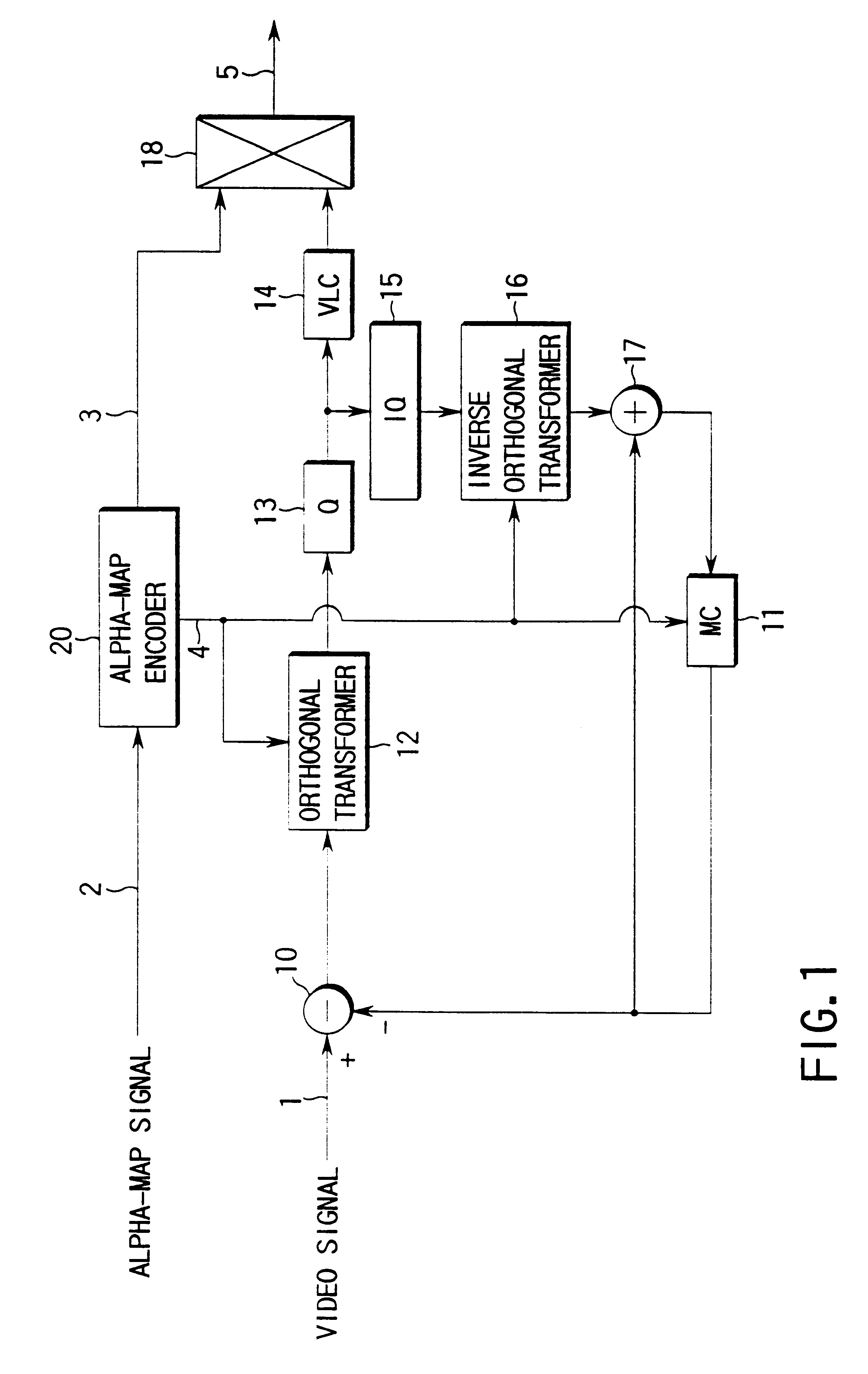
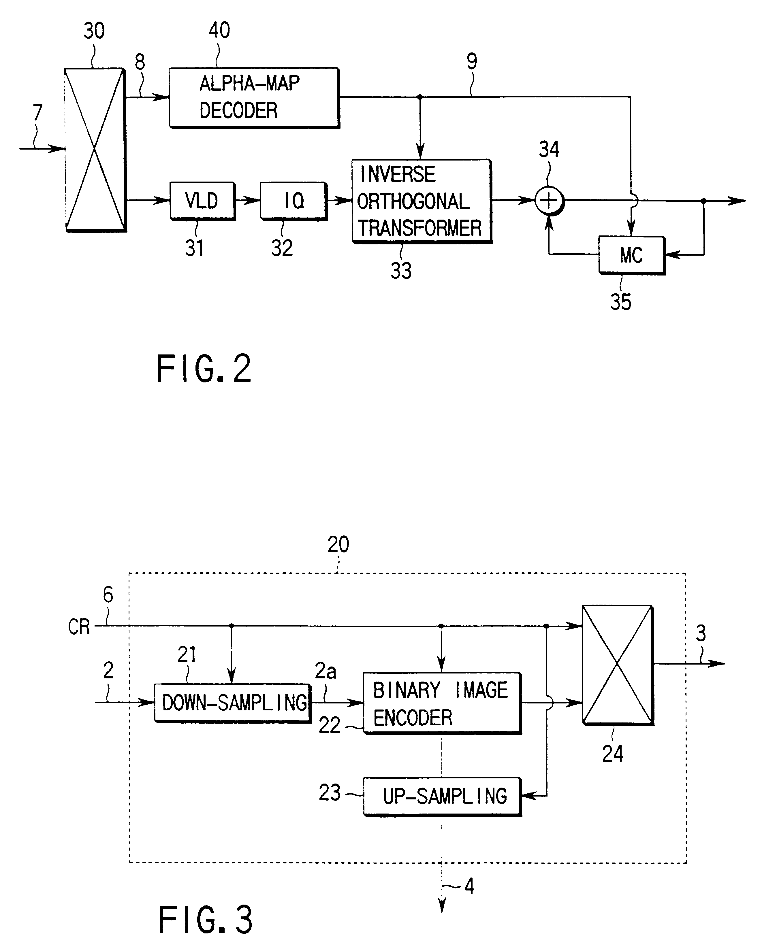
With these circuits, the alpha-map information as subsidiary video information that represents the shape of an object and its position in a frame can be efficiently encoded and decoded.
In this case, upon relative address encoding, a process is done while switching whether a reference change pixel b1 is detected from a "current block" as a block of the currently processed image or from a "compensated block" as a block of the previously processed image in units of blocks, and the encoding side also encodes this switching information. The decoding side decodes the switching information, and can switch whether a reference change pixel b1 is detected from the "current block" or "compensated block" on the basis of the decoded switching information. In this fashion, an optimal process can be done based on the image contents in units of blocks, and encoding with higher efficiency can be attained.
The alpha-map encoding means selects the decoded image of the block from decoded values obtained by replacing all the pixel values in the block by one of binary values, motion estimation / compensation values, and decoded values obtained upon size conversion in units of blocks. Hence, the alpha-map signal can be encoded with high quality and efficiency, and encoding can be done at a high compression ratio while maintaining high image quality.
With these apparatuses, upon encoding an alpha-map in units of macro blocks (divided unit image blocks obtained when an image is divided into units each consisting of a plurality of pixels, e.g., 16.times.16 pixels), unique labels are assigned to the shape modes of the blocks and are encoded, and original alpha-map data is decoded by decoding these labels, thus attaining efficient encoding.

Problems solved by technology

However, in the method of dividing an image in the frame into a background and object, the number of encoded bits increases as compared to the conventional encoding method that simultaneously encodes an image in the frame, since the alpha-map must also be encoded, and the encoding efficiency lowers due to an increase in the number of encoded bits of the alpha-map.

Method used


Image

  • Video encoding apparatus and video decoding apparatus
  • Video encoding apparatus and video decoding apparatus
  • Video encoding apparatus and video decoding apparatus

Examples


first embodiment

The first embodiment is directed to the apparatus for switching a plurality of predetermined variable-length coding tables. FIG. 12 shows an embodiment that dynamically corrects the table in accordance with the frequencies of actually generated symbols. This embodiment has an arrangement in which a counter 72 and a Hoffman table forming circuit 73 is added to the encoding apparatus of the first embodiment shown in FIG. 5.

The counter 72 receives a symbol 57 from the shape mode determination circuit 55 and a context number 74 from the table determination circuit 60. The counter 72 holds the frequencies of symbols in units of context numbers. A predetermined time after this holding, a frequency 75 of each symbol is supplied to the Huffman able forming circuit 73 in units of context numbers. The Huffman table forming circuit 73 forms an encoding table 76 based on Huffman encoding (Fujita, "Basic Information Theory", Shokodo, pp. 52-53, 1987). The table 76 is supplied to the table determ...


PUM


Abstract

An alpha-map encoding apparatus includes a first down-sampling circuit (21) for down-sampling an alpha-map signal which represents the shape of an object and the position in the frame of the object at a down-sampling ratio based on size conversion ratio information, an up-sampling circuit (23) for up-sampling the alpha-map signal at an up-sampling ratio based on size conversion ratio information given to restore the down-sampled alpha-map signal to an original size, and outputting a local decoded alpha-map signal, a motion estimation / compensation circuit (25) for generating a motion estimation / compensation signal on the basis of the previous decoded video signal and a motion vector signal, a second down-sampling circuit (26) for down-sampling the motion estimation / compensation signal at the down-sampling ratio, a binary image encoder for encoding the alpha-map signal down-sampled by the first down-sampling circuit to a binary image in accordance with the motion estimation / compensation signal down-sampled by the second down-sampling circuit, and outputting an encoded binary image signal, and a multiplexer for multiplexing and outputting the encoded binary image signal and the up-sampling ratio information.

Description

The present invention relates to a video encoding apparatus and video decoding apparatus, which encode, transmit, and store video signals with high efficiency, and decode the encoded signals.Since a video signal has a large information volume, it is a common practice to compression-encode the video signal when it is transmitted or stored. In order to encode a video signal with high efficiency, an image in units of frames is divided into blocks in units of a predetermined number of pixels (for example, M.times.N pixels (M: the number of pixels in the horizontal direction, N: the number of pixels in the vertical direction)), each divided block is orthogonally transformed to separate the spatial frequency of the image into the respective frequency components, and these frequency components are acquired as transform coefficients and are encoded.As one of video encoding methods, a video encoding method that belongs to the category called mid-level encoding is proposed in "J. Y. A. Twang ...

Claims


Application Information

Patent Timeline
Patent Type & Authority Patents(United States)
IPC IPC(8): G06T9/00H04N7/26H04N7/46G06T3/40H04N19/50H03M7/36H03M7/42H04N19/107H04N19/13H04N19/134H04N19/136H04N19/14H04N19/166H04N19/167H04N19/176H04N19/186H04N19/196H04N19/20H04N19/423H04N19/46H04N19/463H04N19/503H04N19/51H04N19/517H04N19/52H04N19/59H04N19/60H04N19/61H04N19/65H04N19/68H04N19/70H04N19/80H04N19/85H04N19/91
CPCH04N19/59H04N19/20G06T9/20
Inventor YAMAGUCHI, NOBORUWATANABE, TOSHIAKIIDA, TAKASHIKIKUCHI, YOSHIHIRO
Owner KK TOSHIBA
Learn More