
Method for defining instantaneous value of current of pulse-controlled inductive load

Inactive Publication Date: 2001-02-27
ABB (SCHWEIZ) AG
View PDF8 Cites 7 Cited by
  • Summary
  • Abstract
  • Description
  • Claims
  • Application Information

AI Technical Summary

Benefits of technology

The advantage of the claimed method is that a highly reliable estimate of the load current is obtained by a simple method. Although the cables are long, the load current can be estimated accurately by the method, whereby the dynamic control of the pulsed voltage source can be maintained at a high level under all conditions. The DTC or any current modulation whatsoever can then also be made to work in connection with long cables.
High cabling costs, which would result if the measurement were performed at that end of the supply cable which is close to the load, are avoided by the method of the invention. Further, since the method enables reliable estimation of the current, capacitive components, such as LC low-pass filters or the like, can also be connected to the supply cable where necessary.
The method allows the current of the output of the pulsed voltage source to be measured using a more cost-effective current detector than in the prior art. The highest-frequency components are filtered from the measured current in the method, whereby the bandwidth requirement of the current measurement is notably lower than in the prior art. For the same reason, an AD converter used to modify the current data can be much more cost-effective than in the prior art solutions, in which all the frequencies of the current have been measured as accurately as possible.
The problems caused by the long cables, for example, have made it necessary to restrict the switching frequency of the DTC. On account of the method of the present invention, the length of the minimum pulse of the pulsed voltage source need not be restricted, but due to the accurate current data the switching frequency can be raised arbitrarily high if so desired. The raising of the switching frequency makes it possible to further improve the dynamic accuracy of the control.

Problems solved by technology

In practice, however, the load is often situated at a relatively long distance from the voltage source supplying it.
The modulation basis used is usually the current measured at the end of the voltage source; above a certain length of cable the measurements are so inaccurate due to the current oscillation that the instantaneous value of the load current can no longer be controlled.
When long cables are used, either the dynamics of the control has to be compromised or the current of the load has to be measured separately at the load, whereby expensive separate cabling has to be installed to enable the transfer of the measuring signal.

Method used


Image

  • Method for defining instantaneous value of current of pulse-controlled inductive load
  • Method for defining instantaneous value of current of pulse-controlled inductive load
  • Method for defining instantaneous value of current of pulse-controlled inductive load

Examples


Embodiment Construction

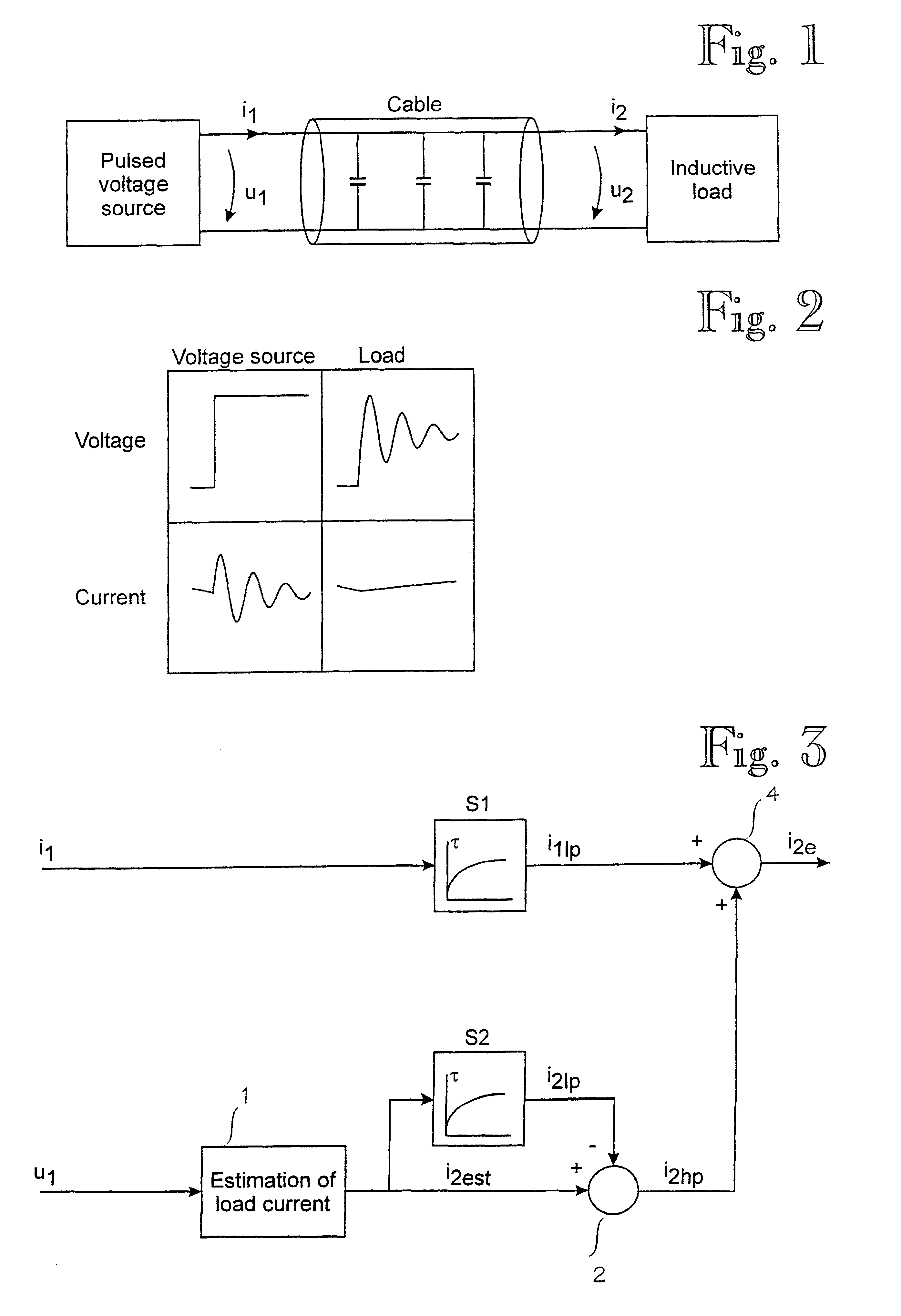
When an inductive load is supplied via a supply cable using a pulsed voltage source as shown in FIG. 1, the output voltage u1 of the pulsed voltage source produces a voltage wave flowing along the cable. The wave is seen as voltage u2 at that end of the cable which is close to the load. The general curves of voltages u1 and u2 are shown in FIG. 2. FIG. 2 also shows the general curves of current i1 of the voltage source and of load current i2.

As shown in FIG. 2, the currents of the voltage source and the load may differ considerably at a given instant. During the switching, part of the current flows via the cable or via other partly capacitive components, which appears as oscillation of the type shown in FIG. 2 in the current measured in the voltage source. Because of the oscillation of the current, any estimates on the instantaneous value of the load current formed on the basis of the output current of the voltage source may be erroneous, and it is then difficult to set the load cur...


PUM


Abstract

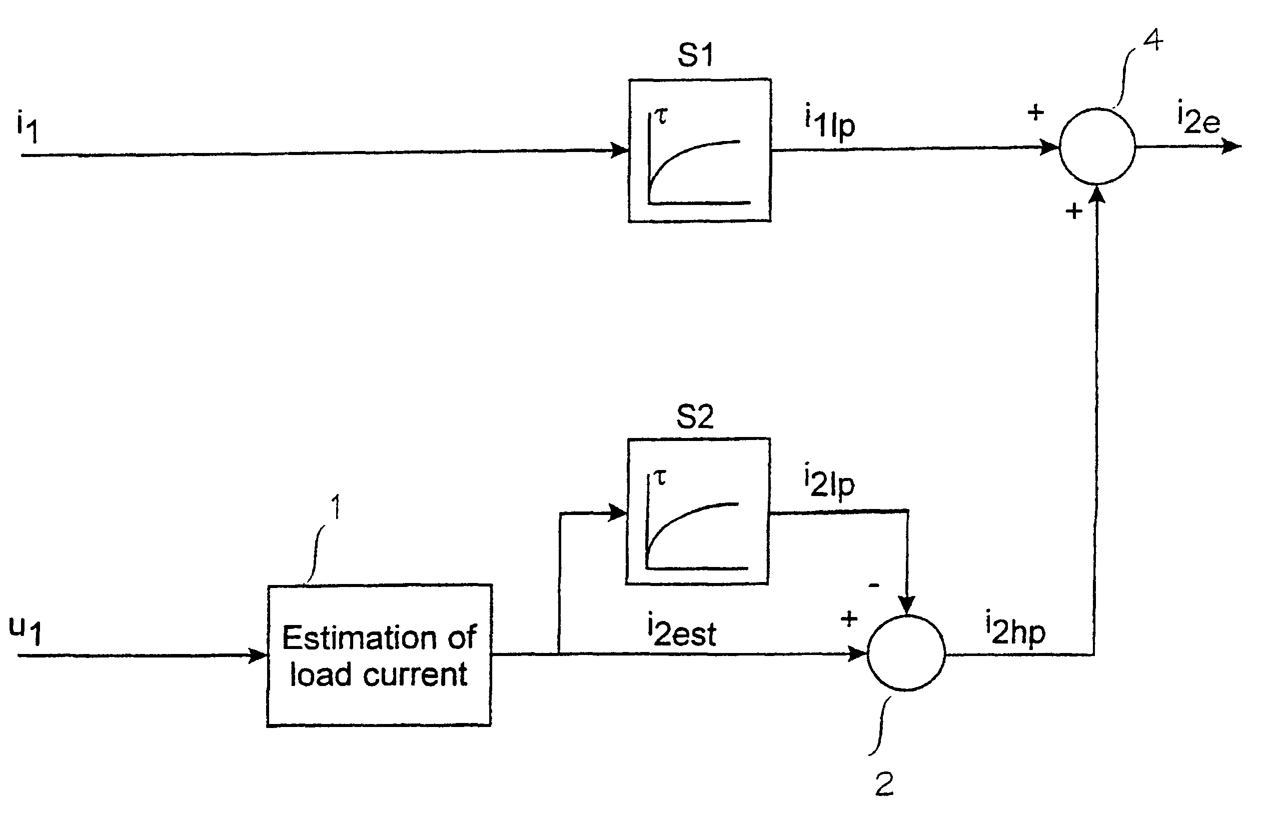
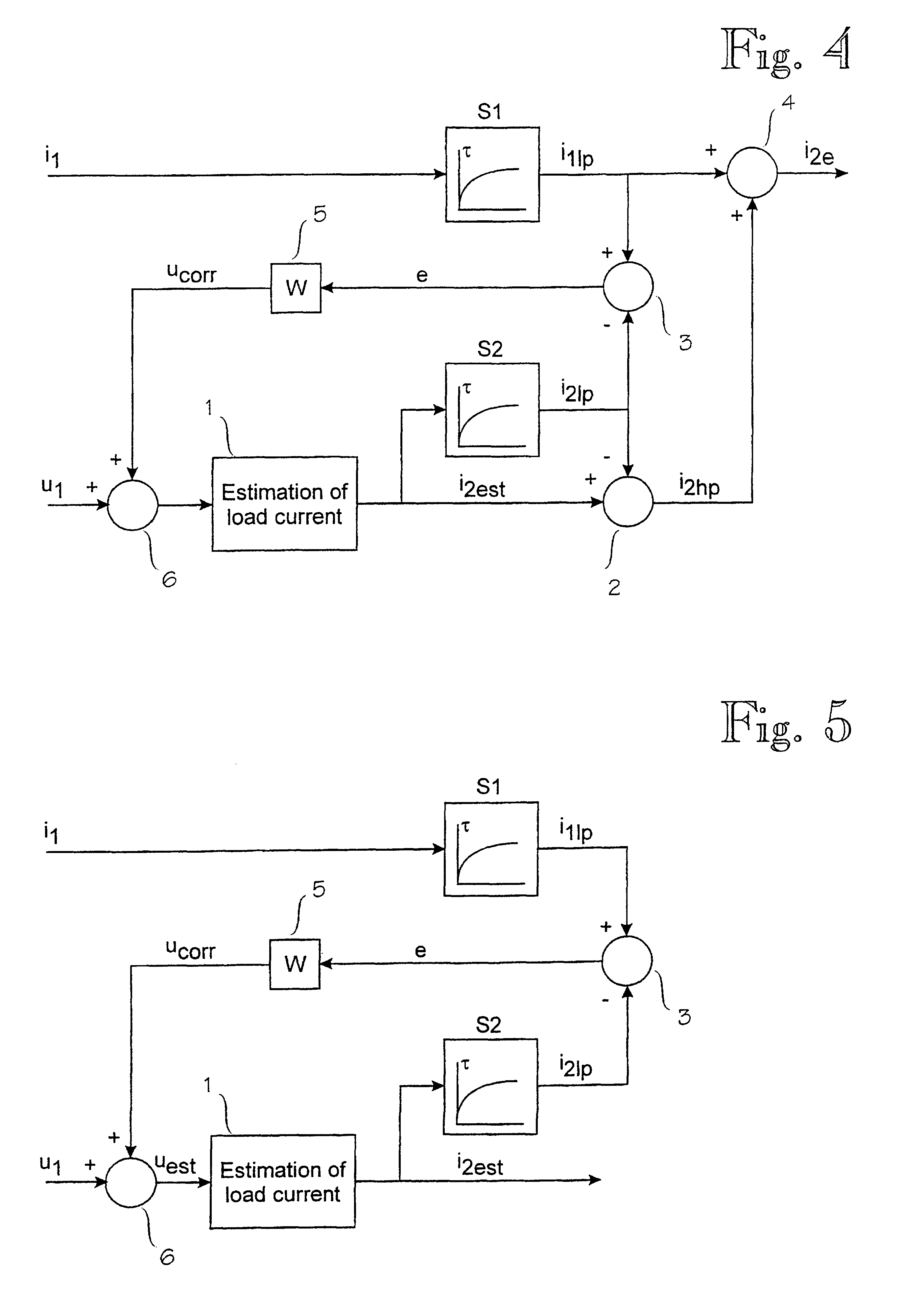
A method of defining an instantaneous value of a current (i2e) of a pulse-controlled inductive load when the impedance of the load is known, the method comprising the steps of: measuring the output voltage (u1) of a pulsed voltage source, and measuring the output current (i1) of the pulsed voltage source. The method is characterized by further comprising the steps of: low-pass filtering the measured output current (i1) of the pulsed voltage source to produce a fundamental wave current (i1lp), defining a load current estimate (i2est) by computation on the basis of the measured output voltage (u1) of the pulsed voltage source and the impedance of the load, high-pass filtering the load current estimate (i2est), and defining the instantaneous value of the load current (i2e) by adding the high-pass-filtered load current estimate (i2hp) to the fundamental wave current (i1p).

Description

BACKGROUND OF INVENTIONThe invention relates to a method according to the preambles of independent claims 1 and 5 for defining an instantaneous value of a current of a pulse-controlled inductive load when the impedance of the load is known, the method comprising the steps ofmeasuring the output voltage of a pulsed voltage source, andmeasuring the output current of the pulsed voltage source.The current or magnetic flux of the inductive load is normally controlled by changing the voltage affecting over the load, the voltage typically consisting of single or multi-level voltage pulses generated by semiconductor switches. The simplest solution is that the switches operate at a fixed switching frequency, whereby the pulse width of the voltage pulses determines the average voltage level in the load. An example for such a pulsed voltage source is a pulse-width-modulated (PWM) voltage source. The current of the load is here quite well controlled dynamically, if the switching frequency is su...

Claims


Application Information

Patent Timeline
IPC IPC(8): G01R19/00
CPCG01R19/0092
Inventor SCHRODERUS, PETRIHEIKKILA, SAMULI
Owner ABB (SCHWEIZ) AG
Learn More