
Oriented film producing facility with thickness and orientation control means

a technology of orientation control and oriented film, which is applied in the field of drawing system, can solve the problems of difficulty in maintaining thickness and degree of orientation in a uniform manner, local fluctuations of thickness and degree of orientation cannot be prevented, and cannot maintain uniform degree of orientation over all the surface area

Inactive Publication Date: 2001-02-20
MITSUI CHEM INC +2
View PDF11 Cites 29 Cited by
  • Summary
  • Abstract
  • Description
  • Claims
  • Application Information

AI Technical Summary

Problems solved by technology

However, there is difficulty maintaining a thickness and an degree of orientation in a uniform manner along a direction perpendicular to a advancing direction of a base film, that is a width direction of the base film.
According to this method, while a thickness and a degree of orientation, as averages, of a drawn film can constantly be maintained, local fluctuations of thickness and degree of orientation cannot be prevented.
If an opening degree of the extrusion mouth of a die is narrowed by an adjust bolt such as a heat bolt, a thickness in a width direction can be controlled, but it entails reduction of a mass per a unit time of a not-oriented film during a time when the die extrusion mouth is narrowed, which is not to maintain a uniform degree of orientation over all the surface area.
Therefore, there is a problem that the film during drawing has a high proportion of break-down by a drawing tension in longitudinal and lateral directions imposed on the film.
If a film is broken, an operation of a drawing system has to be stopped and, a broken film has to be removed, and not only is a time passed but labor is consumed before the system is restarted, which is a problem.
Especially, if a film is broken in a lateral drawing machine, necessary operations cannot be started since a temperature inside the machine is high and thereby there arises a problem that productivity is reduced.
There arises another problem that while a improvement toward a higher speed of drawing is desired for the purpose of cost down, unevenness in thickness and degree of orientation of a film is increased and a probability of film breakdown is increased if drawing is conducted at a high speed.
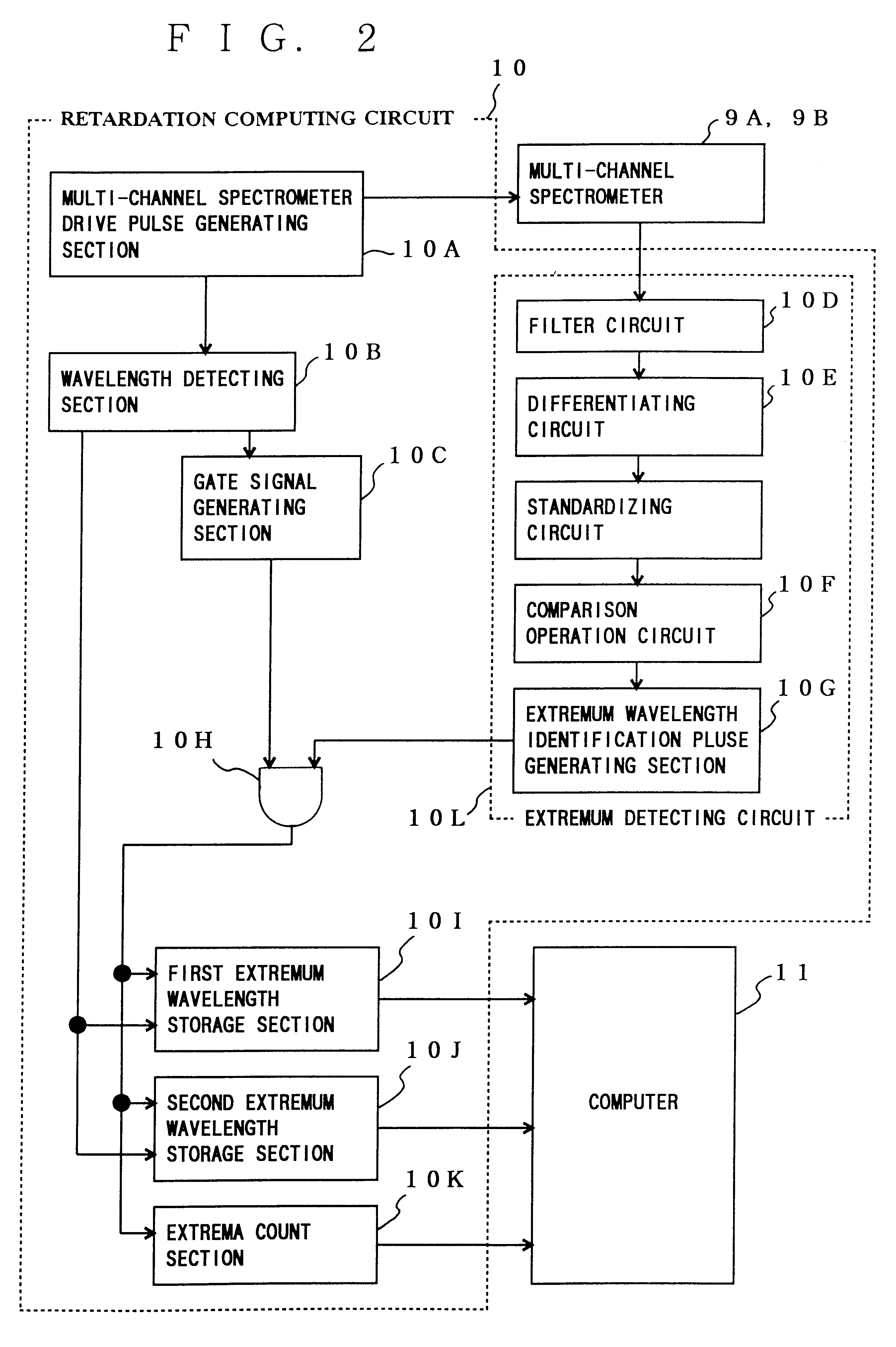
However, in a conventional measuring method for measuring a birefringence, it has been difficult measuring a birefringence in real time since much time is required for operations such as a transfer of transmitted light spectrum data to a computer and data processing in the computer.

Method used


Image

  • Oriented film producing facility with thickness and orientation control means
  • Oriented film producing facility with thickness and orientation control means
  • Oriented film producing facility with thickness and orientation control means

Examples


first and second embodiments

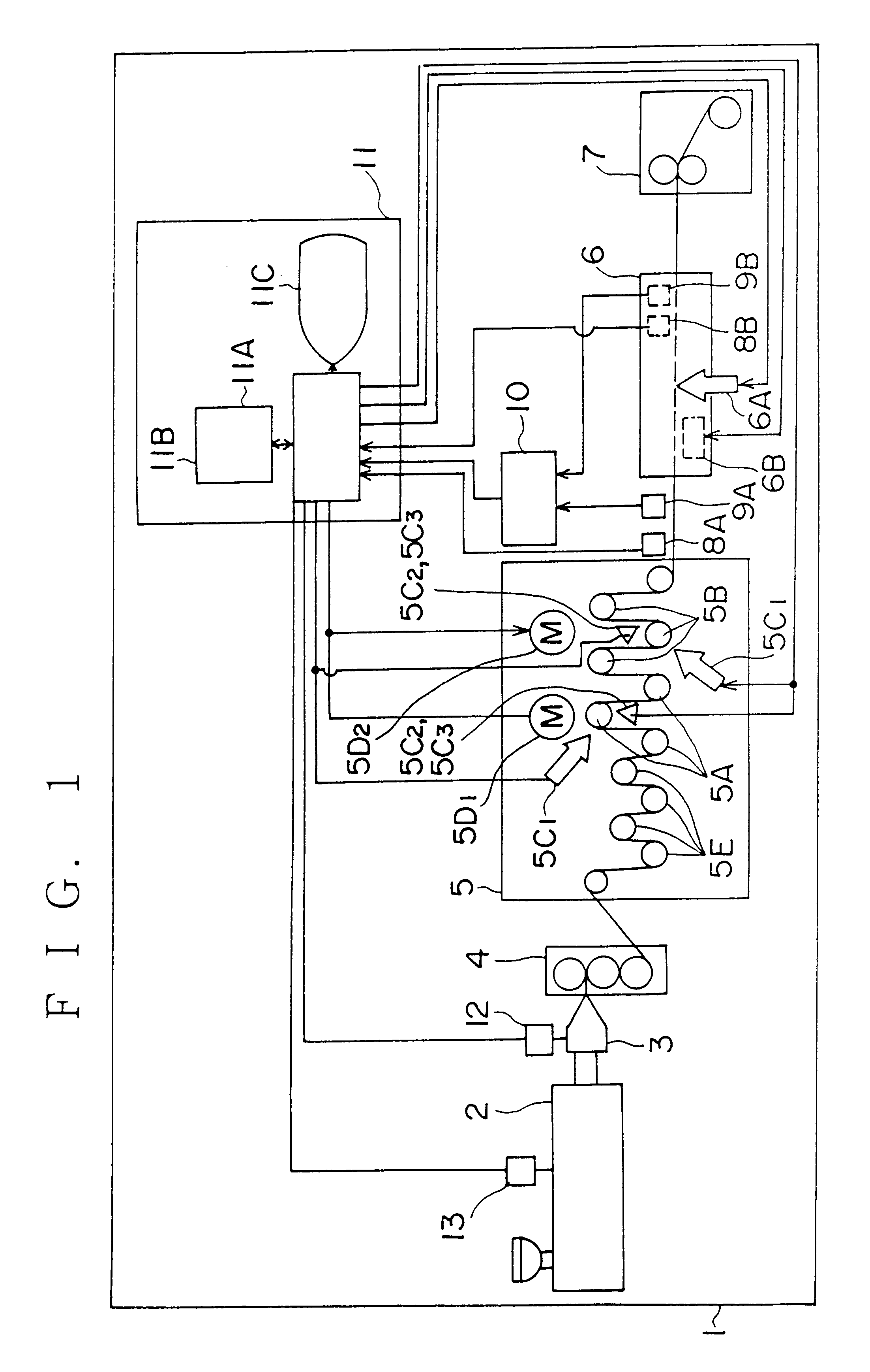
of an oriented film producing facility according to the present invention will be described in reference to FIGS. 1 to 12 below.

first embodiment

The First Embodiment

(1) First of all, an outline of the oriented film producing facility of the first embodiment will be described.

The oriented film producing facility, as shown in FIG. 1, comprises: an extruder 2, a die 3 mounted to an discharging end of the extruder 2; a base film shaping apparatus 4 which cools a not-oriented film discharged through the die 3; a sequential bi-axial drawing machine comprising a longitudinal drawing machine 5 which draws the base film in a longitudinal direction and a lateral drawing machine 6 which further draws a longitudinally drawn film in a lateral direction; and a take-up apparatus 7 which takes up a drawn film.

The oriented film producing facility 1 further comprises: thickness gauges 8A, 8B which measures a film already drawn, longitudinally or laterally; spectrometer 9A, 9B which obtains optical information from a film already drawn, longitudinally or laterally; a retardation processor 10 which computes a phase difference, and which is conn...

second embodiment

The Second Embodiment

(3) Next, an oriented film producing facility according to the second embodiment will be described.

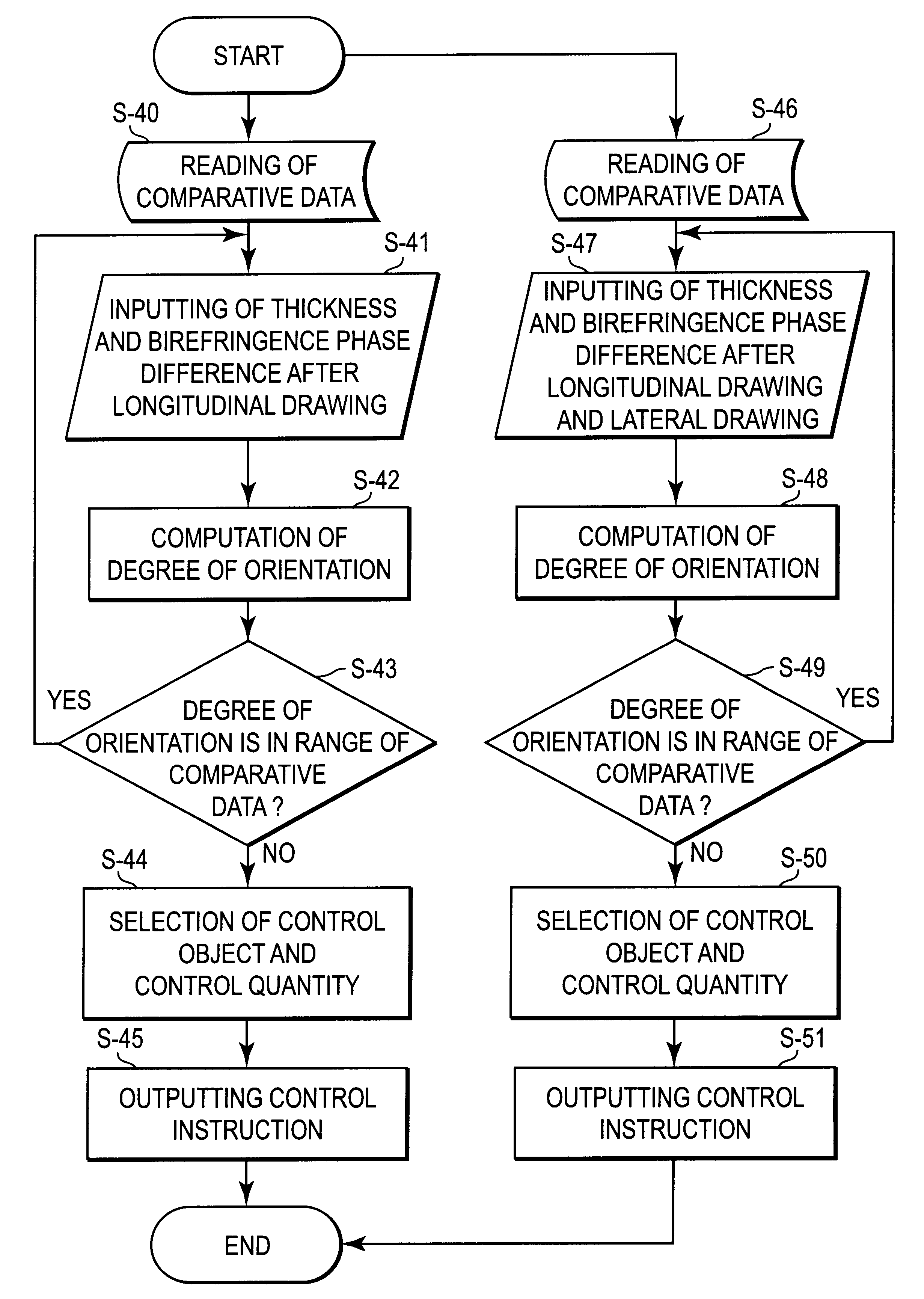
Since a constitution of an oriented film producing facility 1 according to the second embodiment and control operations of an control apparatus 11 thereof are the same as those of the first embodiment and the description is omitted. With respect to measurement of a thickness and degree of orientation, a film is divided to a predetermined blocks and the thickness and degree of orientation are measured on each block in real time.

Then, in the case where an error arises in thickness after lateral drawing, a control operation to change a lateral draw ratio for the lateral drawing machine 6 will be described.

First, in the case where a thickness of a film in a block measured by the thickness gauge 8B disposed at a downstream position of the lateral drawing machine 6 is larger than a preset value, the following means are taken.

As first means, in order to increase a lateral...


PUM

PropertyMeasurementUnit
Timeaaaaaaaaaa
Temperatureaaaaaaaaaa
Thicknessaaaaaaaaaa

Abstract

A drawing system in which a thickness and degree of orientation of an oriented film or the like is maintained in a uniform manner under a condition of a high speed, shortened is a time required from a time when a molding material is charged in an extruder and drawing started until a time when a film is taken up on a take-up apparatus, and a high quality film or the like is produced at a high speed and besides, a probability for a not-oriented or oriented film or the like to be broken down during drawing is reduced. A thickness and degree of orientation of a film are independently measured in thickness gauges and a film orientation measuring apparatus in a continuous manner after longitudinal drawing or lateral drawing and measured values are input to a computer. The computer input with the measured values respectively compares preset target values with the measured thickness and degree of orientation and a control operation to change a longitudinal draw ratio is conducted if the measured values are different from respective preset values based on results of comparison processing.

Description

1. Field of the InventionThe present invention relates to a drawing system in which a thermoplastic resin such as polypropylene, polyethylene or the like is molded into a shape of a film through a die by melt-extrusion with an extruder, a not-oriented film thus molded is drawn at a temperature equal to or lower than a melting point in longitudinal and lateral directions to orient molecules, and to an oriented film producing facility which comprises the drawing system, a measuring apparatus for measuring a thickness and an degree of orientation of a drawn film, and in which facility a predetermined control operation is performed on the drawing system based on measured values.The present invention further relates to a high speed measuring method for measuring a birefringence, especially a birefringence, whose retardation which is larger than a measuring wavelength.2. Description of the Background ArtA film used for packaging and the like has conventionally been produced in such a mann...

Claims


Application Information

Patent Timeline
IPC IPC(8): B29C55/14G01N21/21G01N21/23G01B11/06B29L7/00G01J4/00
CPCB29C55/143G01N21/23B29C47/92B29C2037/90B29C48/08B29C48/92B29C2948/92152B29C2948/92438B29C2948/9259B29C2948/92647B29C2948/92704B29C2948/92885B29C2948/92904B29C2948/92933
Inventor TSUZUKIYAMA, KOJIMOTOOKA, MASANORIFUJIWARA, TOSHIYUKITORIUMI, MICHIO
Owner MITSUI CHEM INC
Learn More