
Multiplex radio transmitter and multiplex radio transmission method, multiplex radio receiver and multiplex radio receiving method, and multiplex radio transceiver and multiplex transmission/receiving system

a radio transmitter and multiplex technology, applied in the field of multiplex radio transmitter and multiplex radio transmission methods, multiplex radio receiver and multiplex radio receiving methods, multiplex radio transceivers and multiplex transmission/receiving systems, can solve the problems of preventing affecting the realization of a band-pass filter capable of being used in all channels, and having a center frequency in a microwave band such as that mentioned abov

Inactive Publication Date: 2001-02-06
FUJITSU LTD
View PDF6 Cites 47 Cited by
  • Summary
  • Abstract
  • Description
  • Claims
  • Application Information

AI Technical Summary

Problems solved by technology

However, according to the existing technique, a narrow-band filter having its center frequency in a microwave band such as that mentioned previously is very expensive and bulky.
Further, since the individual transmission and receiving sections disposed in the multiplex radio transceiver transmit data through use of a plurality of channels of different frequencies, there is a need for a band-pass filter having band-pass characteristics corresponding to each of the channels, thus impeding realization of a band-pass filter capable of being used in all the channels.
Even in such a case, there is a need for a band-pass filter having band-pass characteristics corresponding to each of the channels, thus impeding realization of a band-pass filter capable of being used in all the channels.

Method used


Image

  • Multiplex radio transmitter and multiplex radio transmission method, multiplex radio receiver and multiplex radio receiving method, and multiplex radio transceiver and multiplex transmission/receiving system
  • Multiplex radio transmitter and multiplex radio transmission method, multiplex radio receiver and multiplex radio receiving method, and multiplex radio transceiver and multiplex transmission/receiving system
  • Multiplex radio transmitter and multiplex radio transmission method, multiplex radio receiver and multiplex radio receiving method, and multiplex radio transceiver and multiplex transmission/receiving system

Examples


first embodiment

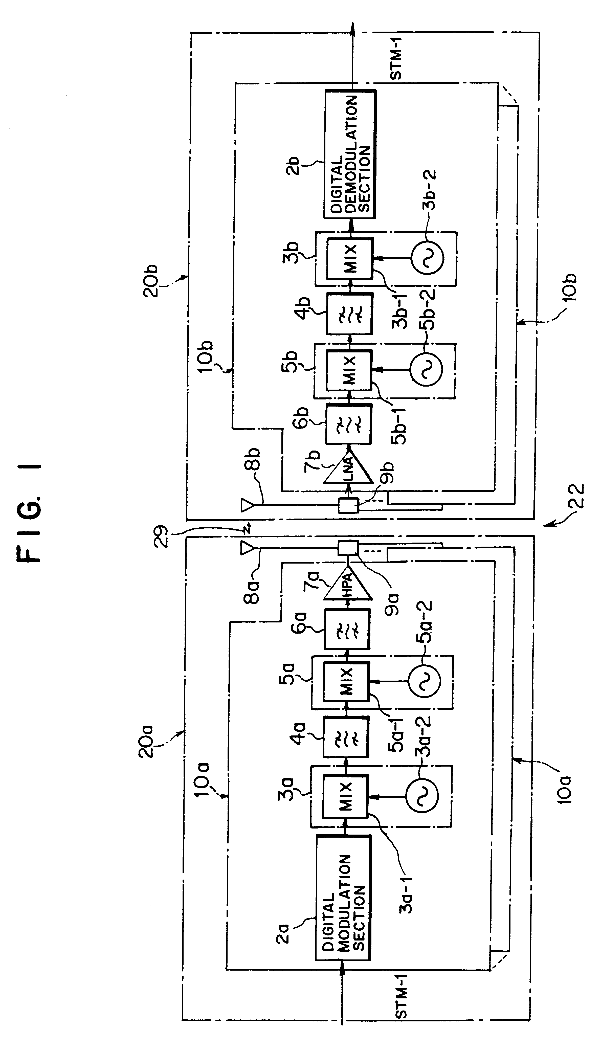
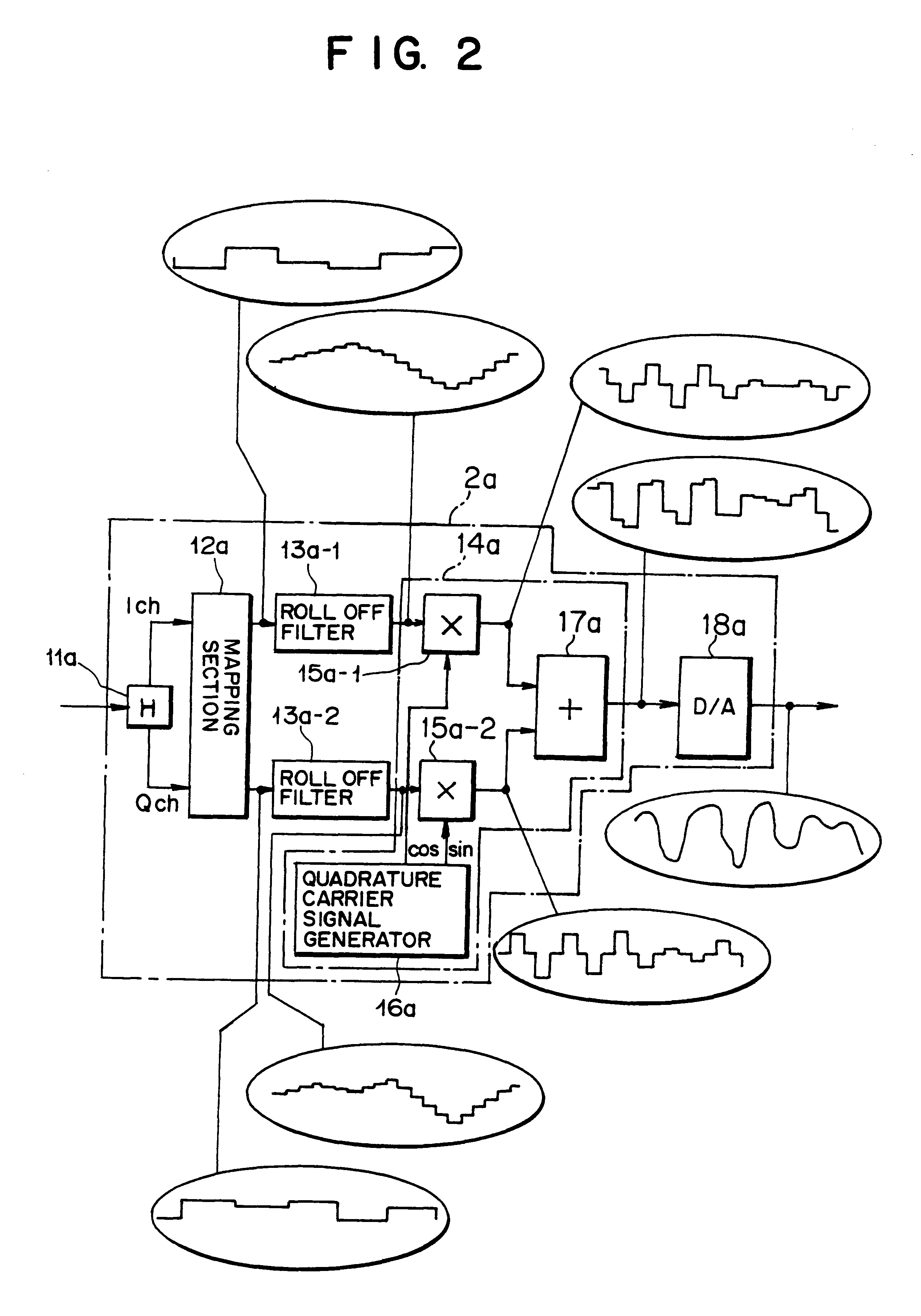
FIG. 1 is a circuit diagram showing the configuration of a trunk multiplex radio transmission / receiving system using a digital modulation scheme according to the present invention. A trunk multiplex radio transmission / receiving system 22 using a digital modulation scheme and shown in FIG. 1 relays multiplexed trunk signal data (STM-1) between synchronous multiplex repeaters or between a synchronous multiplex repeater and a transmission-end apparatus. The trunk multiplex radio transmission / receiving system 22 comprises a multiplex radio transmitter (hereinafter often referred to simply as a "transmitter") 20a which transmits a plurality of channel signals having different frequencies while converting them into a multiplexed signal; a multiplex radio receiver (hereinafter often referred to simply as a "receiver") 20b which receives a plurality of multiplexed channel signals having different frequencies; and a radio propagation path 29.

Here, the transmitter 20a digitally modulates mult...

second embodiment

(B) Description of a Second Embodiment

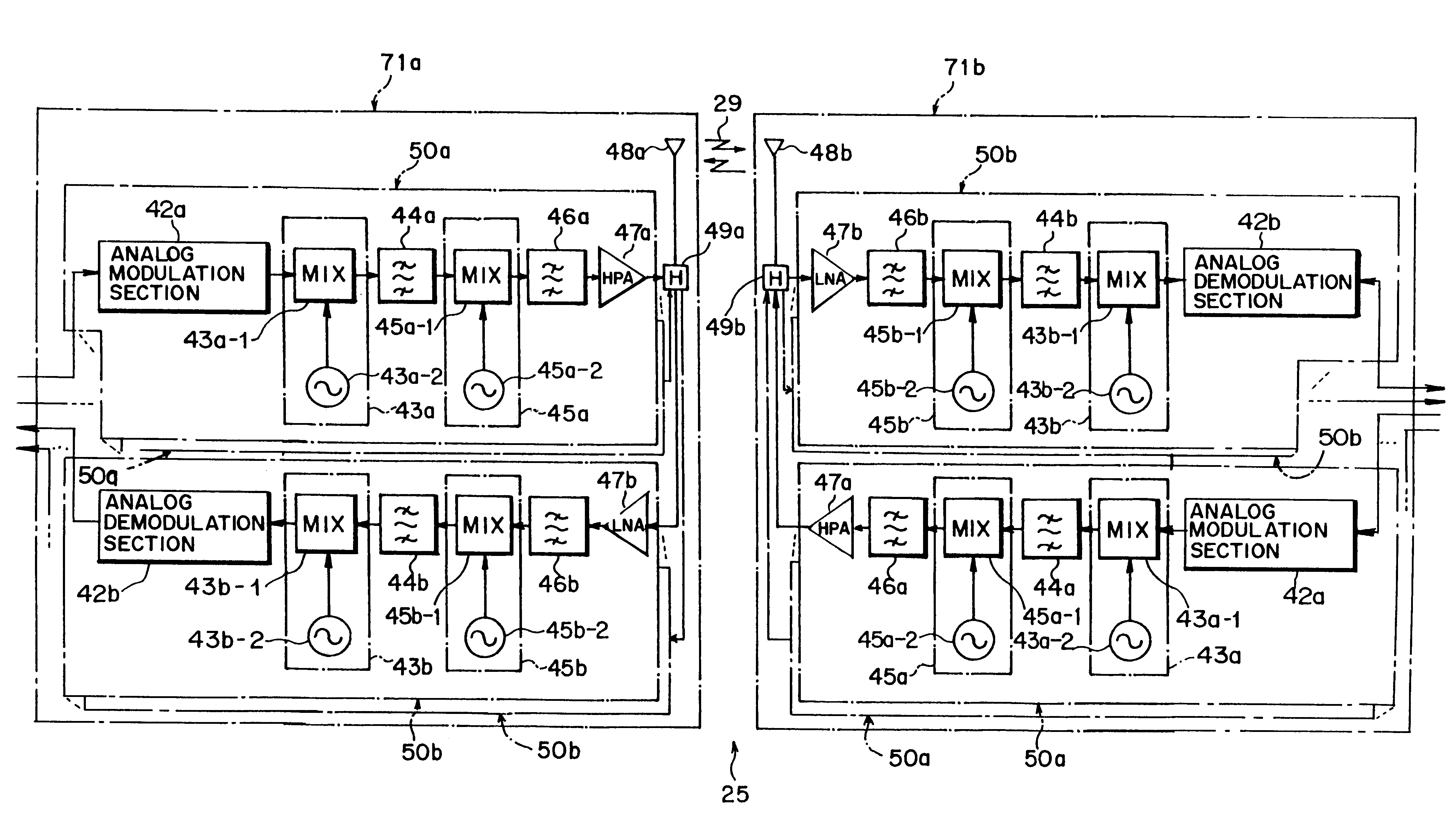
In the first embodiment and its modification set forth, the transmission section of the radio repeater digitally modulates multiplexed trunk signal data (STM-1), and the digitally-modulated signal is up-converted in two steps and then sent to the radio propagation path 29. In contrast, the receiving section of the opposing radio repeater down-converts a received radio frequency (RF) signal in two steps. The thus-converted signal is digitally demodulated and is subjected to a baseband processing treatment, whereby multiplexed trunk signal data (STM-1) are obtained.

In contrast, an analog modulation / demodulation scheme may be alternatively be used.

FIG. 17 is a circuit diagram showing the configuration of a trunk multiplex radio transmission / receiving system using an analog modulation scheme according to a second embodiment of the present invention. A trunk multiplex radio transmission / receiving system 24 using an analog modulation scheme relays mul...


PUM


Abstract

The present invention is directed to a multiplex radio transmission / receiving system. The system includes a plurality of transmission sections provided so as to correspond to a plurality of channels, and a plurality of receiving sections provided so as to correspond to the plurality of channels. Each transmission section includes a modulation section, a first frequency conversion section, a first band-pass filter, a second frequency conversion section, and a second band-pass filter. Each receiving section includes a third band-pass filter, a third frequency conversion section, a fourth band-pass filter, a fourth frequency conversion section, and a demodulation section. By selection of an optimum value for a second intermediate frequency of a transmitter and for a third intermediate frequency of a receiver, a group of transmission radio frequencies (RF) signals and a group of local frequency signals are allocated without overlap. As a result, there can be prepared one type of band-pass filter which has broad band-pass characteristics and which is common among the transmission and receiving sections disposed within the multiplex radio transceiver or among repeaters, thus allowing use of common members.

Description

1) Field of the InventionThe present invention relates to a multiplex radio transmitter and multiplex radio transmission method, a multiplex radio receiver and multiplex radio receiving method, and a multiplex radio transceiver and multiplex transmission / receiving system suitable for use with a trunk multiplex radio communications system.2) Description of the Related ArtIn recent years, when large volumes of information including such as video data are to be transmitted at high speed, a synchronous multiplex transfer mode (Synchronous Transfer Mode) based on a SDH (Synchronous Digital Hierarchy) has been widely used as a method of transmitting information data. Multiplex radio transceivers are usually located on high ground and relay multiplexed trunk signal data at microwave band through use of a synchronous multiplex transfer modeWith regard to frequency bands, the allocation of available channels in individual frequency bands is specified in detail in the form of ITU-R (Internati...

Claims


Application Information

Patent Timeline
Patent Type & Authority Patents(United States)
IPC IPC(8): H04J1/00H04B1/40H04J1/04H04B1/04H04B7/24H04B7/26H04W72/04
CPCH04B1/40H04J1/00
Inventor KIYANAGI, HIROYUKISUZUKI, TOSHIAKISHIBUYA, YASUHIROSUZUKI, HIROSHI
Owner FUJITSU LTD
Learn More