
Cast on-board injection nozzle with adjustable flow area

a technology of injection nozzle and flow area, which is applied in the direction of liquid fuel engines, vessel construction, marine propulsion, etc., can solve the problems of increasing the problem of operation stability, and increasing the manufacturing cost of such a dynamic adjustable system. , to achieve the effect of improving the performance of gas turbine engines, facilitating fabrication, and optimizing cooling air flow

Inactive Publication Date: 2001-02-06
PRATT & WHITNEY CANADA CORP
View PDF15 Cites 95 Cited by
  • Summary
  • Abstract
  • Description
  • Claims
  • Application Information

AI Technical Summary

Benefits of technology

Another object of the invention is to provide a unitary structure of a TOBI nozzle that may be easily secured in position in a gas turbine engine.
A further object of the invention is to provide a TOBI nozzle that is supported by a stator assembly of a gas turbine engine in a cantilevered manner so that the TOBI nozzle is not subjected to thermal stresses caused by temperature differentials and thrust loads.
The performance of the gas turbine engines is improved when the TOBI nozzle with adjustable flow area to optimize cooling air flow therethrough is used. The unitary structure of the TOBI or ROBI nozzle according to the invention can be easily fabricated using the casting process with low manufacturing cost, and is advantageously not subjected to thermal stress caused by temperature differentials. The adjustable flow area feature also enables the TOBI nozzle to be broadly applicable in different types of engines which have various cooling air mass flow requirements.

Problems solved by technology

One substantial problem associated with such systems is the transfer of cooling air from stationary cavities within the engine stator to a rotor assembly for subsequent distribution to the interior of the rotor blades.
The control system for a dynamic air flow adjustment increases problems associated with operation stabilities.
Overall, the manufacturing cost will increase significantly for such a dynamic adjustable system.
However, the problem encountered with a unitary investment-cast TOBI nozzle is that the temperature differential encountered in proximity to the attachment structure adjacent the turbine stator vanes is more severe than the structural integrity of the casting can tolerate.
Obviously, this would require a weldment of the TOBI nozzle which is not only expensive and difficult but it presents problems that should otherwise be avoided.

Method used


Image

  • Cast on-board injection nozzle with adjustable flow area
  • Cast on-board injection nozzle with adjustable flow area
  • Cast on-board injection nozzle with adjustable flow area

Examples


Embodiment Construction

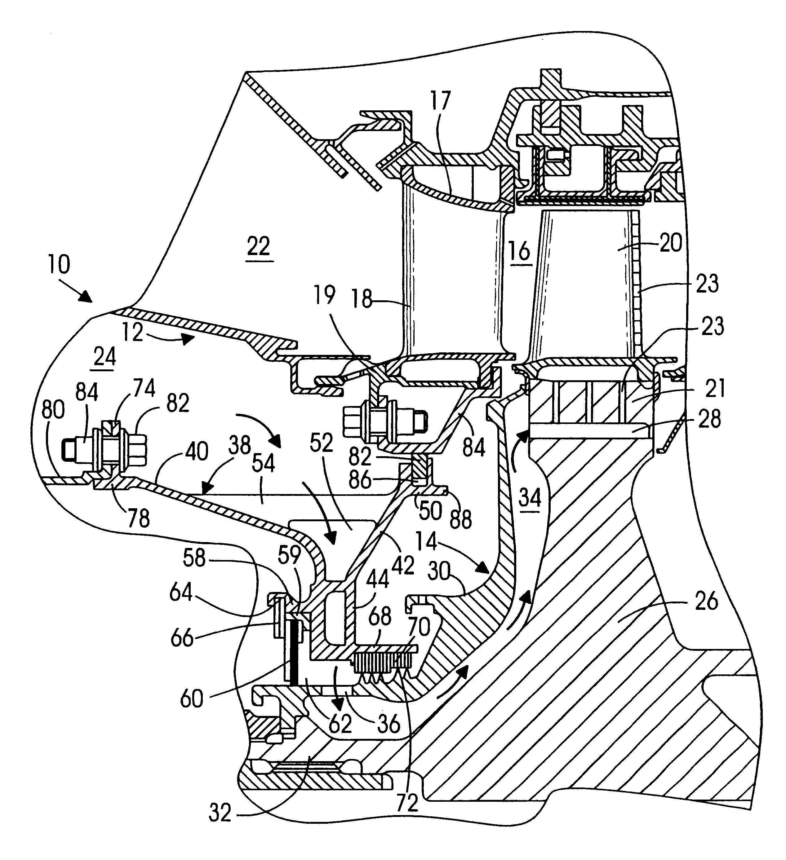
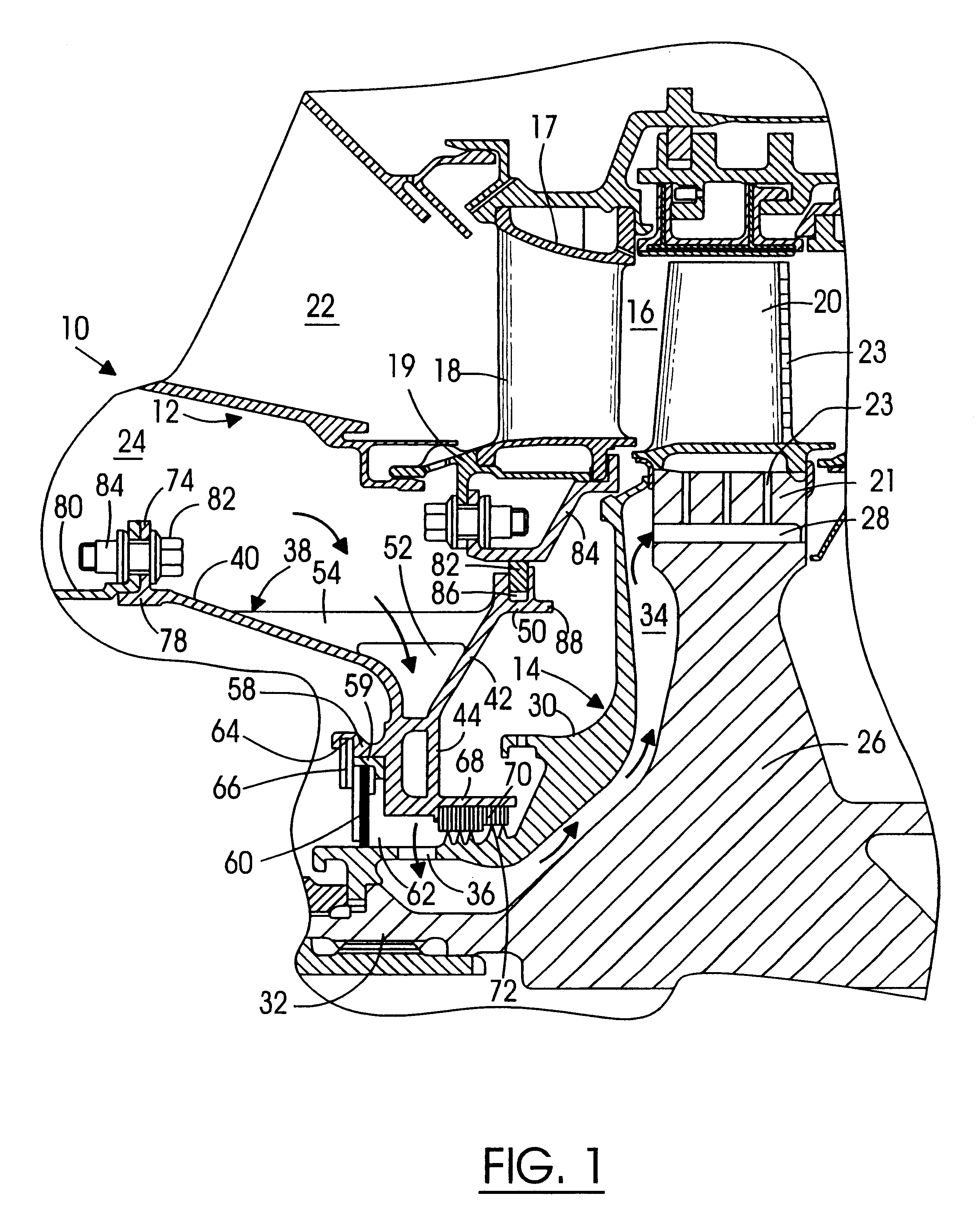
A simplified portion 10 of the turbine section of a gas turbine engine is shown in FIG. 1. Included within the portion shown is a stator assembly 12 and a rotor assembly 14. A flow path 16 for the hot gases is provided downstream of a combustion chamber 22 and defined by the stator assembly 12 including an annular outer flow path wall 17 and an annular inner flow path wall 19. The flow path 16 extends axially between alternating rows of stator vanes, as represented by the single vane 18, and rows of rotor blades, as represented by the single blade 20.

An annular cavity 24 is formed within the stator assembly 12 and it functions in part as a reservoir for turbine cooling air.

Immediately downstream of the row of stator vanes 18 is disposed the row of rotor blades 20. The rotor blades 20 extend radially outwardly from a supporting rotor disk 26 via respective rotor blade roots 21 which are mounted in the supporting rotor disk 26. The supporting rotor disk 26 includes a plurality of inle...


PUM


Abstract

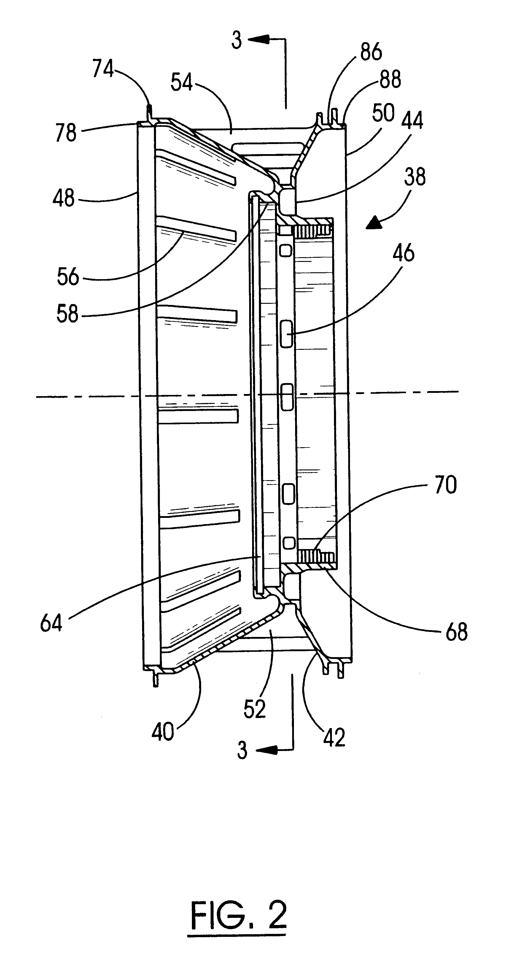
A Tangential On-Board Injection (TOBI) nozzle or a Radial On-Board Injection (ROBI) nozzle with adjustable flow area in a gas turbine engine for directing a cooling air flow into a rotor assembly of the turbine is disclosed. The TOBI or ROBI nozzle is a unitary cast structure including a plurality of tangentially angled cooling air passages, a number of the passages being cast-closed. After a flow test is conducted using the TOBI or ROBI nozzle, one or more of the cast-closed passages may be selectively machined open if the mass flow of the TOBI or ROBI nozzle does not satisfy the design point. Therefore, the structure of the TOBI or ROBI nozzle is easily fabricated using a casting process with low manufacturing costs while the optimum cooling air flow is achieved by adjusting the total flow area of the TOBI or ROBI nozzle before it is installed to the gas turbine engine. Furthermore, the TOBI or ROBI nozzle is advantageously supported in a cantilevered manner to avoid the thermal stress caused by temperature differential. The adjustable flow area feature also enables the TOBI or ROBI nozzle to be broadly used in different types of engines, the required mass flow of which are various.

Description

TECHNICAL FIELDThis invention relates to gas turbine engines and, in particular, to the Tangential On-Board Injection (TOBI) and Radial On-Board Injection (ROBI) nozzle that provides cooling air flow for turbine blades.BACKGROUND OF THE INVENTIONIn gas turbine engines, fuel is burned within a combustion chamber to produce hot gases of combustion. The gases are expanded within a turbine section producing a gas stream across alternating rows of stationary stator vanes and turbine rotor blades to produce usable power. Gas stream temperatures at the initial rows of vanes and blades commonly exceed 2,000.degree. F. Blades and vanes, susceptible to damage by the hot gas stream, are cooled by air compressed upstream within the engine and flowed to the turbine components.One substantial problem associated with such systems is the transfer of cooling air from stationary cavities within the engine stator to a rotor assembly for subsequent distribution to the interior of the rotor blades. For ...

Claims


Application Information

Patent Timeline
IPC IPC(8): F01D5/02F01D5/08F01D5/18F01D11/00F02C7/00F02C7/18F02C7/28F16J15/447
CPCF01D5/08F01D5/087Y02T50/676Y02T50/60
Inventor GLASSPOOLE, DAVID FREDERICKSCHRAENEN, YVAN
Owner PRATT & WHITNEY CANADA CORP
Learn More