Device for producing a leno selvedge, in particular for shuttleless looms

a technology of leno selvedge and loom, which is applied in the direction of weaving, textiles, textiles and paper, etc., can solve the problems of inability to accelerate and slow down in short time intervals, the performance of known motors is achieved only at high cost, and the device too is incapable of fast acceleration and fast slowdown, etc., to avoid thread tear and small mass

Inactive Publication Date: 2000-08-08
GEBR KLOCKER
View PDF5 Cites 3 Cited by
  • Summary
  • Abstract
  • Description
  • Claims
  • Application Information

AI Technical Summary

Benefits of technology

is therefore to develop a device of the above-mentioned type, so that on one hand it has a small mass in order to be able to produce a correct full leno selvedge even in fast running looms, and that it additionally is able to compensate fluctuations in the thread tension of the leno threads, avoiding thus the tear of the threads.
Thanks to the elastic flexibility of the guide elements in the axial direction of the rotating element and to the corresponding deformation of the guide elements, the otherwise occurring fluctuations in thread tension of the leno threads are compensated.
The elastic and flexible arms are advantageously provided at their ends with eyes through which the leno threads are passed. The arms themselves can be of light design, since they are hardly ever subjected to stress. They thus represent a relatively neglectable mass. That means that a small motor with a correspondingly smaller rotor can be chosen, the mass being accordingly small, since, due to the arrangement of the arms on the rotor, the technical designer is now free, except for the output requirements, to choose the size and the diameter of the motor. That's why motors with a small diameter and with accordingly small moved masses can be used without risking to impede a correct shed aperture, since the length of the arms arranged on the rotor permits to choose freely the spacing of the eyes in the arms and thus the size of the shed aperture. Thus it is also possible to untwist the leno threads by designing the rotor so that its rotating direction is invertable.
According to an advantageous characteristic of the invention, the rotor has, in the area of its rotational axis, an advantageous centrical boring for passing the leno threads. That means that the leno threads can be passed through the rotating element by a boring provided centrically on it, improving thus the thread guiding, particularly with regard to a possible twisting in the area of the boring in the rotor.
More particularly, the arms are arranged on the front side of the rotor of the electromotor, this side facing the material; hereby each arm is designed as a hook at its ends, whereas the eye for passing the leno threads is provided in the area of the hook-shaped curve. The eye can be provided with inserts that reduce wear and tear of the eye due to the guiding of the leno threads; sleeve-like inserts made or ceramic materials have particularly been thought of.

Problems solved by technology

That means that such a device has a mass so big that it is physically impossible to accelerate and slow down in short time intervals.
This device too is incapable of fast acceleration and fast slowing down due to the movable mass.
Due to the high mass of the douping disc and of the rotor respectively, this performance can be achieved with known motors only at high cost.
The danger incurred in this case is that, if the rotor and thus the douping disc are given a smaller diameter, the shedding occurring between the two leno threads guided through the douping disc is not sufficient, so that the weft thread cannot be inserted accurately.
Moreover, the threads can still stick together, impeding the formation of a clean selvedge.
The fluctuations in the thread tension may bring sensitive yarns to tear.

Method used


Image

  • Device for producing a leno selvedge, in particular for shuttleless looms
  • Device for producing a leno selvedge, in particular for shuttleless looms
  • Device for producing a leno selvedge, in particular for shuttleless looms

Examples


Embodiment Construction

)

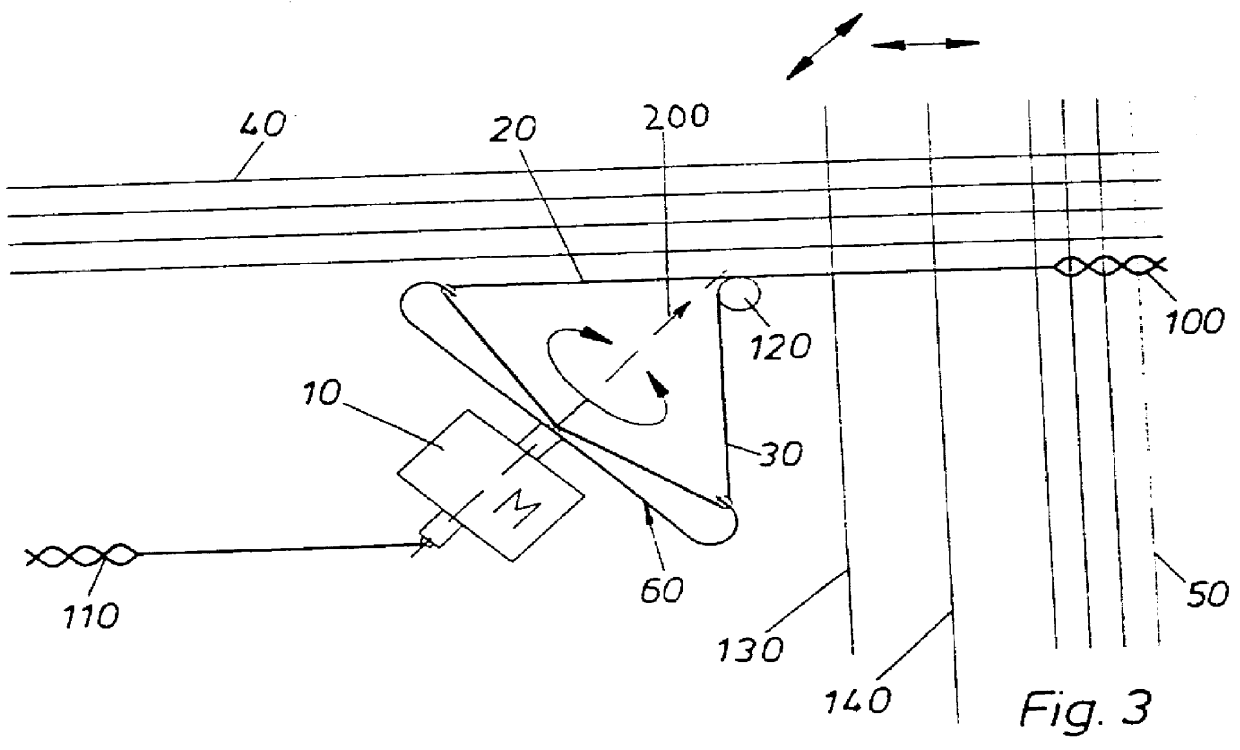
In the device 1 shown in the FIGS. 1 to 3, a motor referred to as a whole with numeral 10 is provided, which has a centrical boring 11 for passing the leno threads 20, 30. In the embodiment shown in FIG. 1, where the rotational axis is transversal to the warp threads 40, that means that it runs essentially parallel to the weft threads 50, two pairs of arms 60, 70 are provided. Each pair of arms 60, 70 consists of two arms 61, 62 and 71, 72 respectively. The two pairs of arms 60, 70 are running parallel to each other and are fastened each on the front side of the rotor 10, as can clearly be seen on FIG. 1. The arms 61, 62 and 71 72 resp. are hook-shaped and have in the area of the hook-shaped curve the eyes 73, 74 and 63, 64 resp. These eyes serve for passing the leno threads 20, 30, which are unwinded from the thread spools 80, 90.

Moreover, the arms 61, 62 and 71 resp. are designed in axial direction (arrow 200) of the rotating element 10 as being elastic and flexible in order to b...


PUM


Abstract

PCT No. PCT / DE96 / 01908 Sec. 371 Date Jun. 5, 1998 Sec. 102(e) Date Jun. 5, 1998 PCT Filed Oct. 3, 1996 PCT Pub. No. WO97 / 24480 PCT Pub. Date Jul. 10, 1997Device for producing a leno selvedge, in particular for a loom, including an electromotor with a rotor, whereas the rotor has at least two spaced guide elements for the leno threads, whereas the guide elements are designed as being elastic and flexible so that they can compensate fluctuations in thread tension in direction of the electromotor's, axis.

Description

1. Field of the Invention.This invention relates to a device for producing a leno selvedge, in particular for a loom, including an electromotor with a rotor, whereas the rotor has at least two spaced guide elements for the leno threads.2. Description of the Prior Art.A device for producing a leno selvedge is known out of FR-A 23 90 524, this device having arms being elastic and flexible in axial direction. This device is a so-called "planet rotator." Due to its design, such a planet rotator has a high mass, still increased by the fact that this known planet rotator has the spools for the leno threads arranged directly on the rotator. That means that such a device has a mass so big that it is physically impossible to accelerate and slow down in short time intervals.The same applies to DE-A 15 35 579 which also shows a so-called planet rotator. This device too is incapable of fast acceleration and fast slowing down due to the movable mass. No other evaluation can be made of U.S. Pat. ...

Claims


Application Information

Patent Timeline
IPC IPC(8): D03C7/00D03C7/04D03C7/08
CPCD03C7/04
Inventor KLOCKER, MATTHIASSCHWEMMLEIN, CHRISTOPHHOCKEMEYER, KURT
Owner GEBR KLOCKER
Why Eureka
Try Eureka