Signal processing apparatus

a technology of signal processing and signal processor, which is applied in the field of signal processing apparatuses, can solve the problems of inability to meet the needs of different image formats, inability to use parallel processor elements satisfactorily, and inability to increase the number of parallel processor elements

Inactive Publication Date: 2000-03-14
SONY CORP
View PDF6 Cites 14 Cited by
  • Summary
  • Abstract
  • Description
  • Claims
  • Application Information

AI Technical Summary

Problems solved by technology

On the other hand, even if the lateral length in FIG. 1 is extended, i.e., the number of parallel processor elements is increased, an increased number of parallel processor elements does not contribute to the performance of the processor since the parallel processor elements are used in correspondence to the number of pixels in one horizontal scanning period of a video signal to be applied thereto.
Thus, to improve the performance of the processor thus configured, such methods are considered as faster instruction cycles, parallel configuration of ALUs, or parallel configuration of the whole processor, however, these methods have problems in hardware.
Also, since the parallel processor elements in the processor having the above described architecture are used in correspondence to the number of pixels in one horizontal scanning period of a video signal to be applied thereto, the processor has a problem in view of versatility in that the number of the parallel processor elements cannot be corresponded to any number of pixels in one horizontal scanning period.
Specifically, if the number of parallel processor elements is matched with the number of pixels in one horizontal scanning period of a particular image format, the parallel processor elements may be excessive or lacking for different image formats.
Thus, the parallel processor elements cannot always be utilized satisfactorily.

Method used


Image

  • Signal processing apparatus
  • Signal processing apparatus
  • Signal processing apparatus

Examples


first embodiment

(1-3) Operation of First Embodiment

In the foregoing configuration, when the video signal processor 20 is supplied with a standard TV signal as the video signal D.sub.IN1, the first selector 24 selects the second switching terminal, and the second selector 25 selects the first switching terminal, whereby the first and second blocks 21, 22 perform respective predetermined processing on the video signal D.sub.IN1. Then, the video signal processor 20 sends the output D.sub.OUT.sub.2 of the second block 22 thus produced as an output signal D.sub.OUT.sub.3 to the outside through the signal output terminal 26.

On the other hand, if an HDTV signal is supplied as the video signal D.sub.IN1, the first block 21 processes the former half of the video signal D.sub.IN1 in one horizontal scanning period, while the second block 22 processes the latter half of the same. Subsequently, the former half and the latter half of the video signal D.sub.IN1 are returned to the original time serial arrangement...

second embodiment

(2-4) Operation of Second Embodiment

Next, the operation of the video signal processor 40 according to the second embodiment will be described with reference to FIGS. 9, 11, 12.

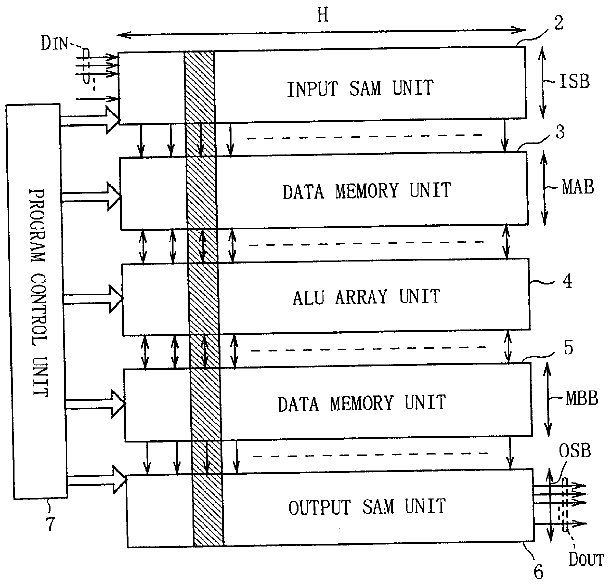
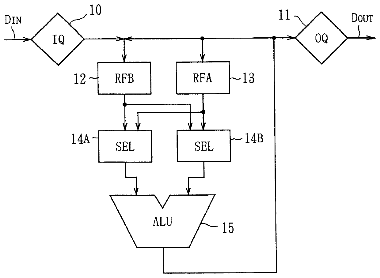
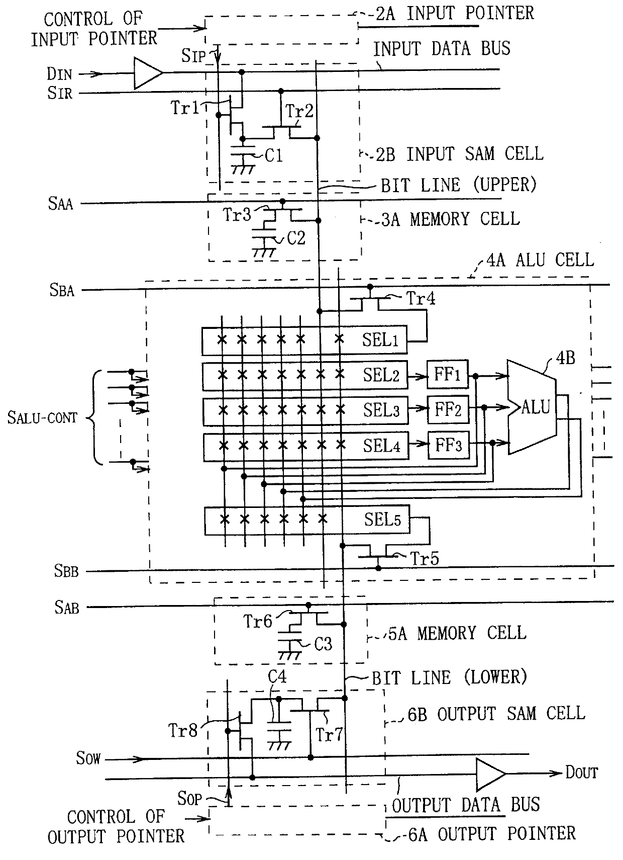
An input video signal D.sub.IN3 is led to the input SAM unit 43 through the input data bus. A write operation control performed on an input SAM cell 72 by the input pointer 71 is the same as that of the structural example of FIG. 1.

Since the number of laterally arranged processor elements is equal to or larger than the number (H) of pixels in one horizontal scanning period of the video signal D.sub.IN3, the video signal D.sub.IN3 is continuously written into the input SAM cells 72 in the right direction during one horizontal scanning period with a clock commensurate with the data rate of the video signal D.sub.IN3, thereby, one horizontal scanning period portion of the input data is accumulated in the input SAM unit 43. This input operation is repeated every horizontal scanning period.

The operation of the prog...

third embodiment

(3) Third Embodiment

(3-1) Configuration of Video Signal Processor According to Third Embodiment

FIG. 16 illustrates a video signal processor 90 according to a third embodiment. This video signal processor 90 is composed of blocks 91-96 each comprising a multiple parallel DSP processor having a large number of bit processing processor elements arranged in one-dimensional array. A total of six blocks 91-96 are arranged in an array having two blocks in the lateral direction and three blocks in the vertical direction.

More specifically, in the video signal processor 90, a signal input terminal 100 is connected to an input terminal of a first block column 101 formed of the first--third blocks 91-94 (corresponding to an input terminal of the first block 91) and to a first switching terminal of a first selector 24. An output terminal of the first block column 101 (corresponding to an output terminal of the third block 93) is connected to a second switching terminal of respective first and se...


PUM


Abstract

A multiple parallel digital signal processor having a large number of bit processing processor elements arranged in one-dimensional array is treated as a processor block, and a plurality of the processor blocks are connected in sequence, while removing redundancy, to form a processor block column. A plurality of processor blocks are connected in sequence such that a processor block at a subsequent stage is supplied either with output of a processor block at a previous stage or with input data, and any of outputs of the processor block columns is delivered as a final output, thereby making it possible to realize a signal processing apparatus which has high performance, versatility, and simple configuration.

Description

1. Field of the InventionThe present invention relates to signal processing apparatuses, and more particularly to an improvement of DSP-LSI (Digital Signal Processor -Large Scale Integrated circuit), for example, incorporated in electronic equipment such as television receivers, video tape recorders, set top boxes, multimedia computers, broadcasting equipment, and so on.2. Description of the Related ArtConventionally, a configuration of a processor for realizing programmable digital signal processing for video signals such as television signals and so on is implemented by a linear array type processor employing an SIMD control (Single Instruction stream Multi Data stream: a parallel processing control for associatively operating all processor elements by a single program). For example, U.S. Pat. No. 4,939,575, which was issued on Jul. 3, 1990, discloses a configuration of this type of processor.The above-mentioned processor has an operator array formed of one-bit ALUs (Arithmetic Lo...

Claims


Application Information

Patent Timeline
IPC IPC(8): G06F17/10H04N5/926H04N5/14H04N11/00H04N5/46G06T1/20G06F15/80
CPCG06F17/10H04N5/14H04N5/926H04N5/46H04N11/002H04N11/24
Inventor IWASE, SEIICHIROKUROKAWA, MASUYOSHIYAMAZAKI, TAKAOOHKI, MITSUHARU
Owner SONY CORP
Why Eureka
Try Eureka