Method of offshore mounting a wind turbine

Pending Publication Date: 2022-10-27
SIEMENS GAMESA RENEWABLE ENERGY AS
View PDF0 Cites 0 Cited by
  • Summary
  • Abstract
  • Description
  • Claims
  • Application Information

AI Technical Summary

Benefits of technology

The present invention offers a faster, simpler and more cost-effective method for installing wind turbines. It uses a floating vessel for the purpose of installation, which can make a "float over" installation of the foundation, such as the monopile or tower, which is a faster and safer method. The installation time is faster, and the installation can be optimized accordingly with regards to weather conditions. The invention requires fewer vessels, crew, and maintenance on the tower. It also allows for the use of a smaller, lighter gripper tool or crane. The floating vessel can be moved due to waves, wind, or other factors, and the tower and nacelle can also be moved to compensate for any horizontal shifts. The invention also includes a slip-joint interface that allows for larger tolerances and facilitates the use of a floating vessel. Overall, this invention offers a more efficient, cost-effective, and safer way to install wind turbines.

Problems solved by technology

For other offshore foundations, the steps after mounting the foundation are similar, but the installation of alternative foundations is likewise time consuming as they require a step of preparing the sea ground prior to mounting the foundation and a step of providing jacket structures and a step of additionally securing the jacket structures to the sea ground.
Another issue pertaining to wind turbine installations occurs during the placement of the nacelle on the top tower section.
This additional lifting height to meet the required clearance can be quite high which increases the complexity of the installation and also the requirement of a lifting crane.
It is to be noted that the conventional use of the jack-up legs is very time consuming.

Method used


Image

  • Method of offshore mounting a wind turbine
  • Method of offshore mounting a wind turbine
  • Method of offshore mounting a wind turbine

Examples


Embodiment Construction

[0054]The illustrations in the drawings are schematically. It is noted that in different figures, similar or identical elements are provided with the same reference signs.

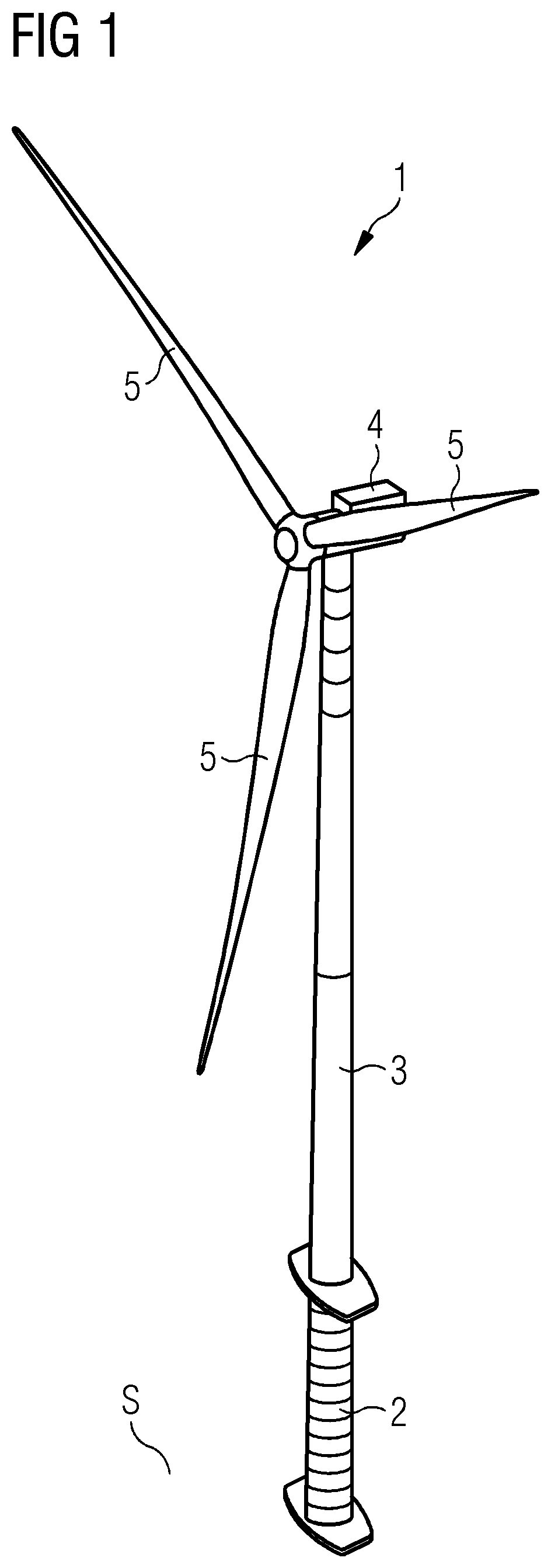
[0055]FIG. 1 shows a wind turbine 1. The wind turbine 1 comprises a foundation 2 mounted to a sea ground S, a tower 3, a nacelle 4 and a plurality of blades 5, for example three blades 5.

[0056]The tower 3 is mounted to the top of the foundation 2, and the nacelle 4 is mounted to the top of the tower 3. The nacelle 4 is mounted rotatable with regard to the tower 3 by means of a yaw bearing. The plurality of blades 5 is mounted to the nacelle 4 by means of a rotatable hub.

[0057]The wind turbine 1 furthermore comprises a generator to convert the rotational energy from the hub into electrical energy in the shape of an AC power.

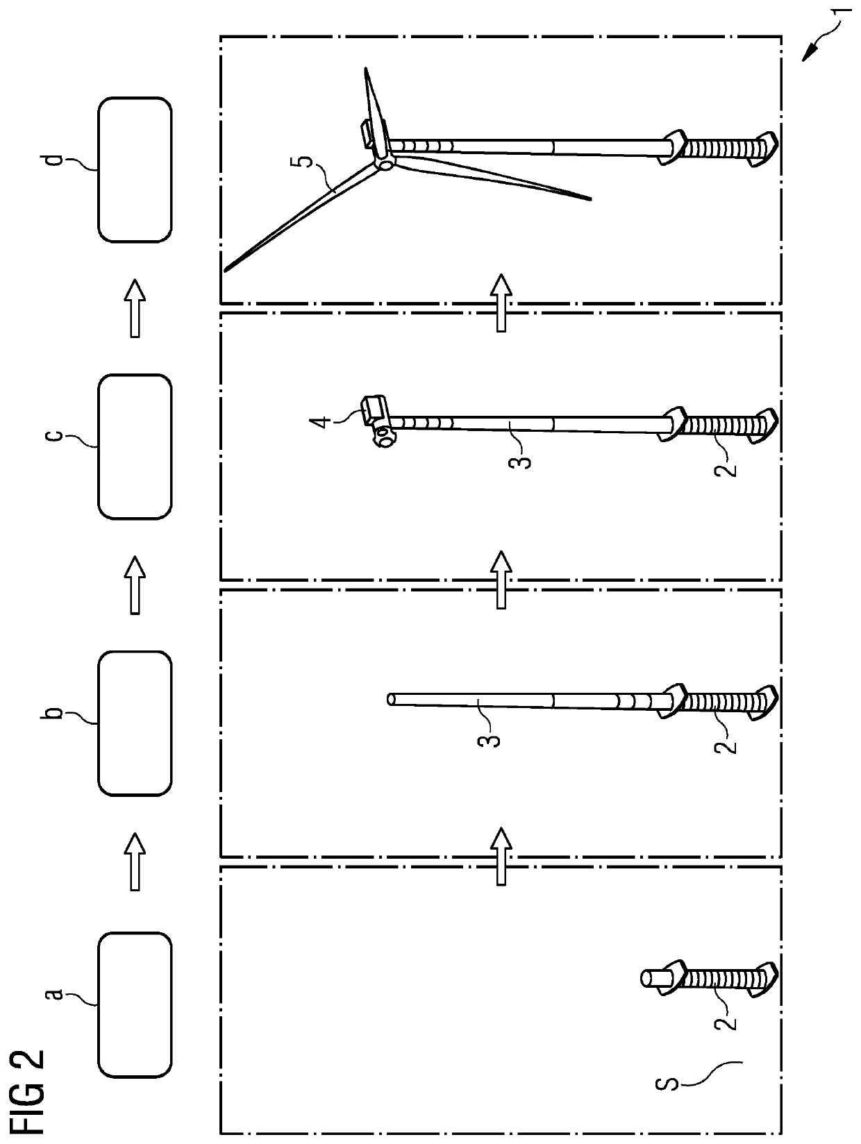
[0058]FIG. 2 shows flowchart comprising steps of a method of offshore mounting a wind turbine 1 according to an embodiment of the present invention. The method comprising steps of: a) mounting th...


PUM


Abstract

A method of offshore mounting a wind turbine, the wind turbine including a foundation, a tower, a nacelle and a plurality of blade is provided. The method includes the steps of: a) mounting the foundation on a sea ground; b) mounting the tower to the foundation; c) mounting the nacelle to the tower; and d) mounting the plurality of blades to the nacelle. At least one of the steps a) through c) is performed by use of at least one floating vessel which is exclusively supported by buoyancy when performing the at least one of the steps a) through c).

Description

CROSS-REFERENCE TO RELATED APPLICATIONS[0001]This application claims priority to PCT Application No. PCT / EP2020 / 072499, having a filing date of Aug. 11, 2020, which claims priority to EP Application No. 19197475.7, having a filing date of Sep. 16, 2019, the entire contents both of which are hereby incorporated by reference.FIELD OF TECHNOLOGY[0002]The following relates to a method of offshore mounting a wind turbine.BACKGROUND[0003]FIG. 22 shows a flowchart of a conventional method of offshore mounting a wind turbine according to the prior art. In a step S1, a monopile is mounted to a sea ground by use of a jack-up vessel. In a step S2, a transition piece is mounted to the top of the monopile by means of the jack-up vessel. In a step S3, the transition piece is grouted by use of the jack-up vessel. In a step S4, the grout is cured for a certain time. In a step S5, a tower is mounted to the transition piece by use of the jack-up vessel. In a step S6, a nacelle is mounted to the top o...

Claims


Application Information

Patent Timeline
IPC IPC(8): F03D13/10F03D13/25
CPCF03D13/10F03D13/25F05B2240/95F05B2240/912F05B2230/6102Y02E10/72Y02E10/727F03D13/116E04H12/342
Inventor SKJAERBAEK, POULSOERENSEN, JOHNNY
Owner SIEMENS GAMESA RENEWABLE ENERGY AS
Why Eureka
Try Eureka