
Hair-cutting unit for use in a hair-cutting appliance

a hair-cutting unit and hair-cutting technology, applied in the direction of metal working devices, etc., can solve the problems of skin irritation, need to avoid skin irritation during shaving action, etc., and achieve the effect of reducing hair-cutting performance, significantly reducing skin irritation resulting from skin cutting

Pending Publication Date: 2022-10-27
KONINKLJIJKE PHILIPS NV
View PDF0 Cites 0 Cited by
  • Summary
  • Abstract
  • Description
  • Claims
  • Application Information

AI Technical Summary

Benefits of technology

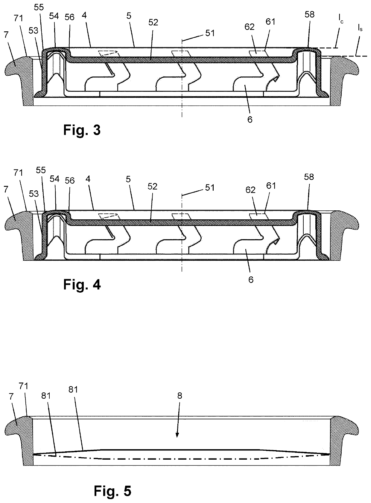
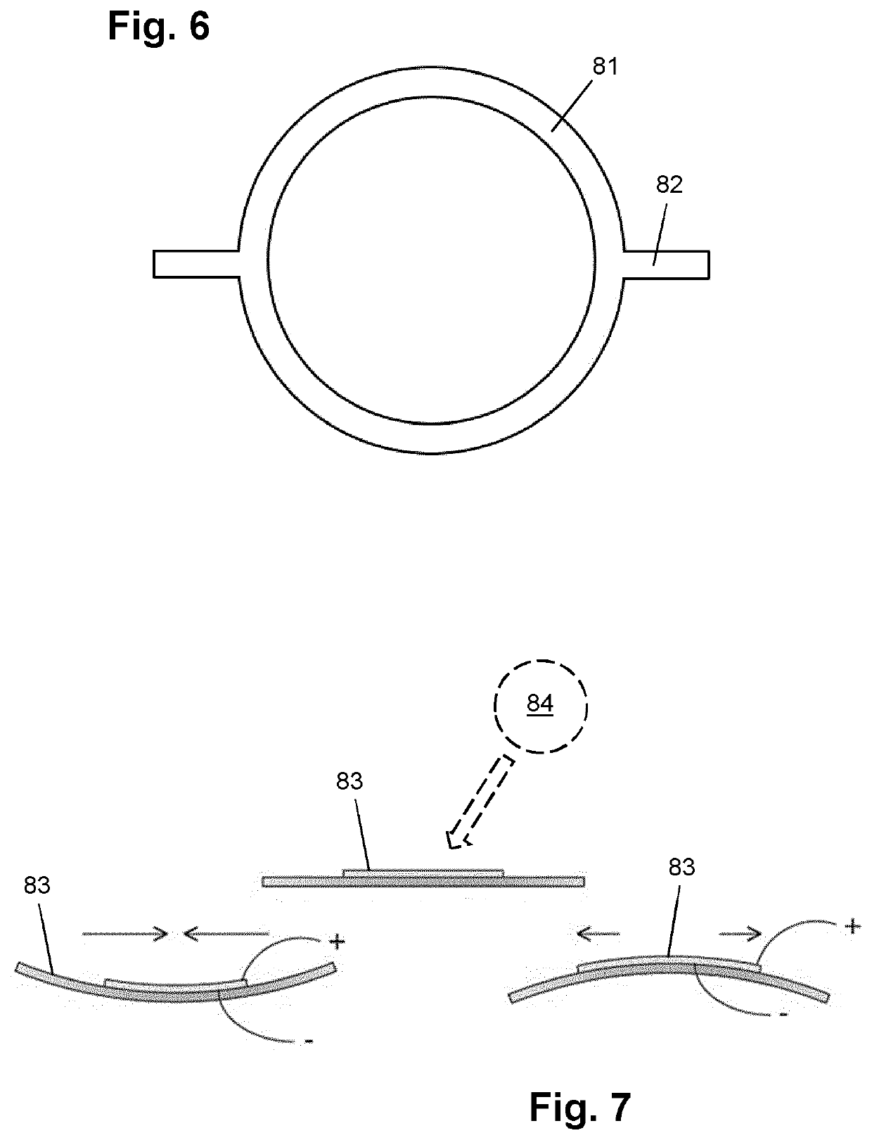
The invention is a hair-cutting unit for a hair-cutting appliance that reduces skin irritation while still achieving optimal hair-cutting performance. It includes a safety mechanism that decreases the level of exposure of the external cutting member when the pressure exerted on the skin increases, preventing skin protruding inside the external cutting member and minimizing skin irritation. The safety mechanism allows the external cutting member to jump between the default position and the retracted position in relation to the contact pressure. The invention also includes a feedback system that provides feedback to the user when the pressure exerted on the skin exceeds a predefined threshold, allowing the user to adjust their behavior to avoid excessive contact pressure and achieve the best hair-cutting results with minimal skin irritation.

Problems solved by technology

In the field of electric rotary shavers, the need to avoid skin irritation during a shaving action is an important issue.
Research has shown that skin irritation can result from a number of phenomena which may occur during a shaving action, including hair manipulation, skin manipulation and skin cutting.

Method used


Image

  • Hair-cutting unit for use in a hair-cutting appliance
  • Hair-cutting unit for use in a hair-cutting appliance
  • Hair-cutting unit for use in a hair-cutting appliance

Examples


Embodiment Construction

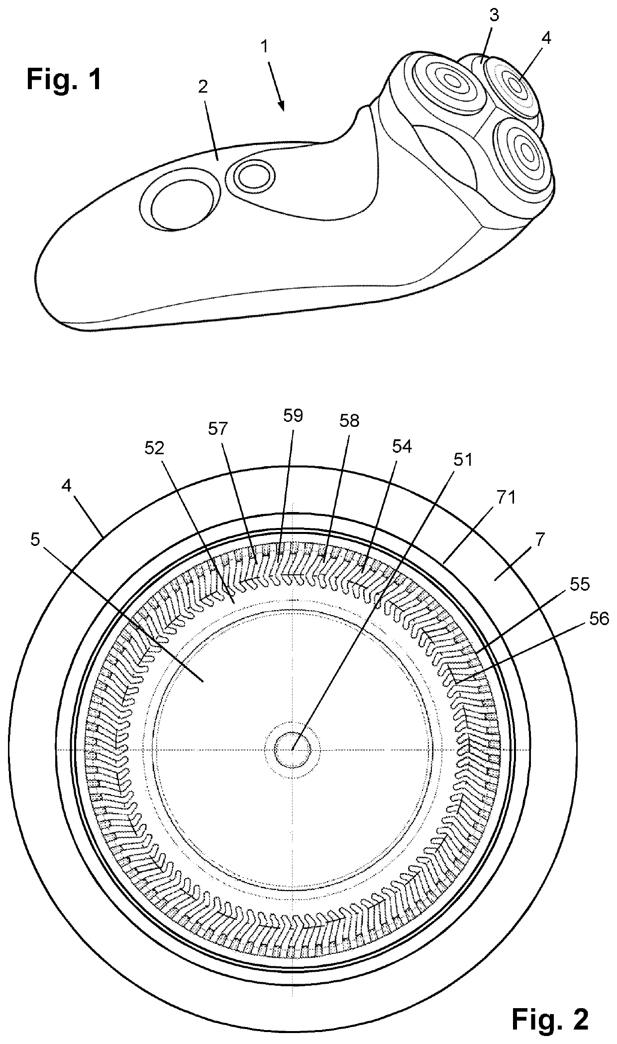
[0025]FIG. 1 shows a shaving appliance of the rotary type as a practical example of a hair-cutting appliance 1. The hair-cutting appliance 1 comprises a body 2 which is intended to be taken hold of by a user of the hair-cutting appliance 1, and a head 3 which is intended to be pressed against a skin area to be subjected to a hair-cutting action. The body 2 of the hair-cutting appliance 1 is also commonly referred to as handle. For various reasons such as a need to service and / or clean the head 3, a need to replace the head 3 by a head of another type, etc., it is practical if the head 3 is removably or hingably mounted to the body 2. The head 3 includes a number of hair-cutting units 4, the number being three in the shown example. When the hair-cutting appliance 1 is applied for the purpose of subjecting a skin area to a hair-cutting action, the actual process of cutting off hairs protruding from the skin area takes place at the position of the hair-cutting units 4.

[0026]With refere...


PUM


Abstract

A hair-cutting unit (4) for use in a hair-cutting appliance comprises an external cutting member (5) having hair-entry openings in a cutting track surface (58), an internal cutting member (6) having at least one hair-cutting element and being movable with respect to the external cutting member (5), and a skin-supporting structure (7) having a skin-supporting surface (71) for contacting a portion of skin to be subjected to a hair-cutting action. The external cutting member (5) is displaceable relative to the skin-supporting structure (7), and the hair-cutting unit (4) further comprises a safety mechanism which is designed to enable stepped and instantaneous variation between at least two discrete stages of a level (lc) of the cutting track surface (58) with respect to a level (ls) of the skin-supporting surface (71), in relation to pressure exerted by the external cutting member (5) on the skin.

Description

FIELD OF THE INVENTION[0001]The invention relates to a hair-cutting unit for use in a hair-cutting appliance, comprising an external cutting member having hair-entry openings in a cutting track surface, an internal cutting member having at least one hair-cutting element and being movable with respect to the external cutting member, and a skin-supporting structure having a skin-supporting surface for contacting a portion of skin to be subjected to a hair-cutting action.[0002]Further, the invention relates to a hair-cutting appliance such as a shaving appliance, comprising at least one hair-cutting unit as mentioned.BACKGROUND OF THE INVENTION[0003]The invention is in the field of hair-cutting appliances, particularly hair-cutting appliances which are designed to perform shaving actions and the like in which hairs are cut at a position close to the skin. In general, a hair-cutting appliance comprises a head where one or more hair-cutting units are located. A particularly common design...

Claims


Application Information

Patent Timeline
Patent Type & Authority Applications(United States)
IPC IPC(8): B26B19/14B26B19/38
CPCB26B19/145B26B19/143B26B19/388B26B19/3806
Inventor VAN DIEST, MIKEPRAGT, JOHNKLEIN HORSMAN, MARTIJN DIRKJENKINS, MICHAEL REECE
Owner KONINKLJIJKE PHILIPS NV
Learn More