
Marine propulsion device

Pending Publication Date: 2022-10-06
YAMAHA MOTOR CO LTD
View PDF0 Cites 0 Cited by
  • Summary
  • Abstract
  • Description
  • Claims
  • Application Information

AI Technical Summary

Benefits of technology

This patent aims to enhance the efficiency of drive torque in marine propulsion devices. The technical effects aim to improve the transfer of power from the engine to the propeller, resulting in more effective and efficient operation.

Problems solved by technology

As a result, the loss of drive torque transmitted from the drive shaft to the propeller shaft increases.

Method used


Image

  • Marine propulsion device
  • Marine propulsion device
  • Marine propulsion device

Examples


Embodiment Construction

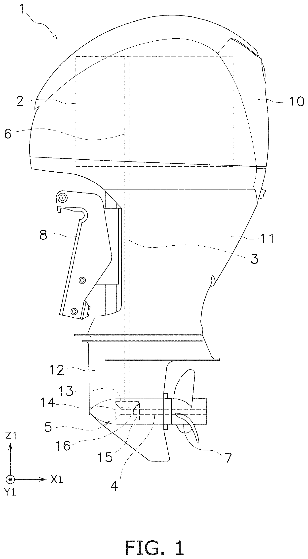
[0019]Hereinafter, preferred embodiments of the present invention will be described with reference to the drawings. FIG. 1 is a side view of a marine propulsion device 1 according to a first preferred embodiment. The marine propulsion device 1 according to the present preferred embodiment is an outboard motor. The marine propulsion device 1 is attached to a stern of a boat via a bracket 8.

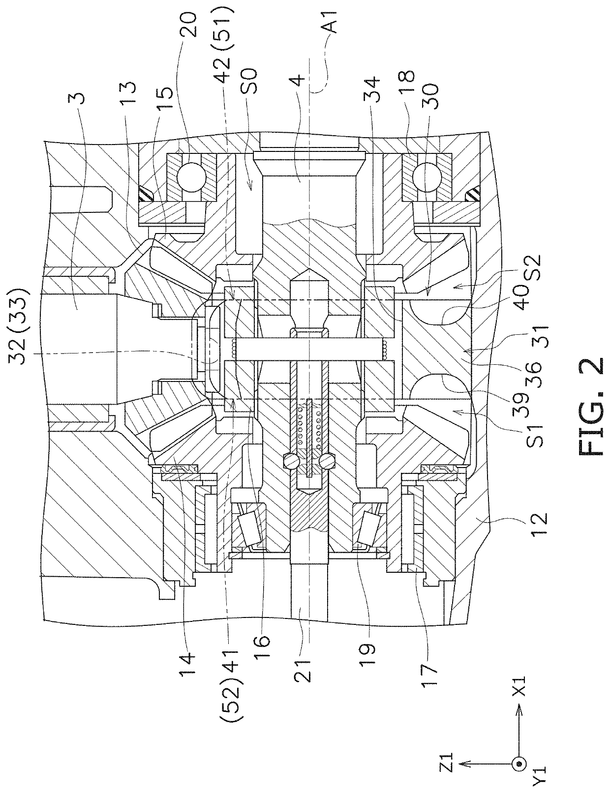
[0020]The marine propulsion device 1 includes a drive source 2, a first shaft 3, a second shaft 4, and a shift mechanism 5. The drive source 2 includes, for example, an internal combustion engine. Alternatively, the drive source 2 may include an electric motor. The first shaft 3 is connected to the drive source 2. The first shaft 3 extends in a first axial direction Z1. In the present preferred embodiment, the first axial direction Z1 is the vertical direction of the marine propulsion device 1. The drive source 2 includes a crank shaft 6. The crank shaft 6 extends in the first axial direction Z1. T...


PUM


Abstract

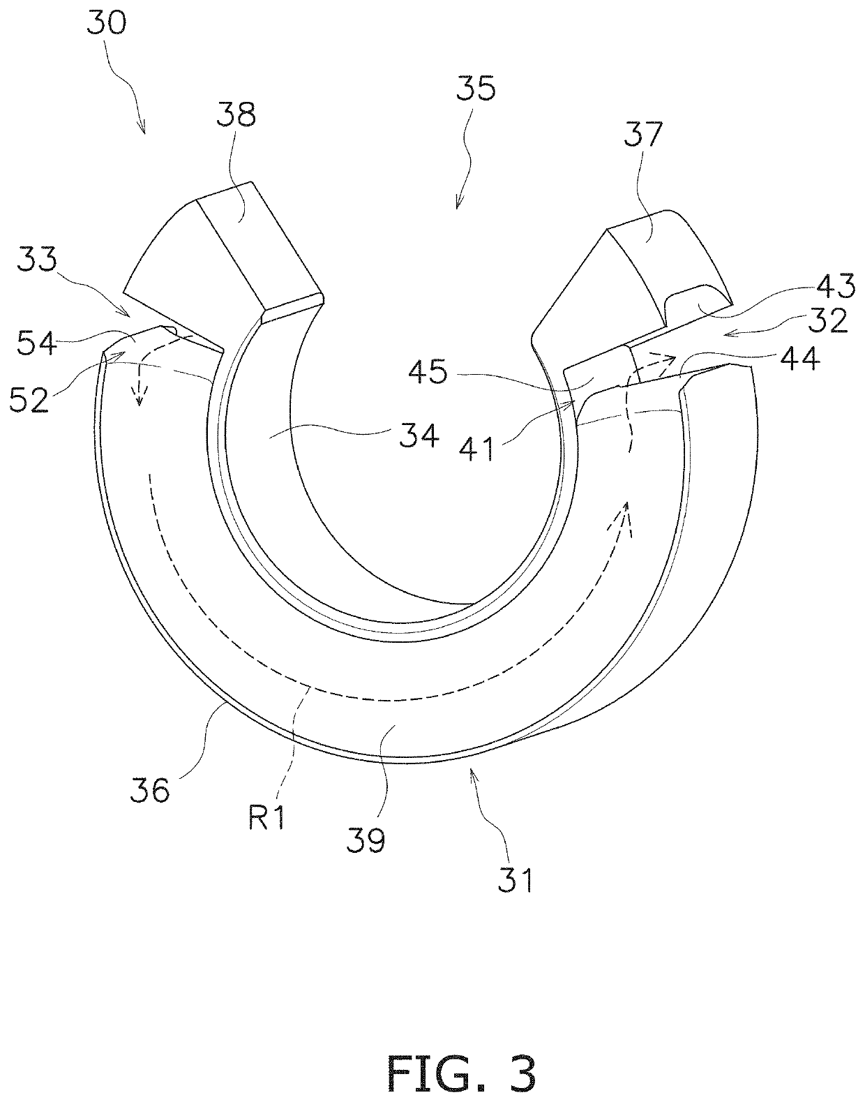
A marine propulsion device includes a first gear, a second gear, a third gear, a case, a partition wall, and a first flow path. The case includes an internal space in which the first gear, the second gear, and the third gear are located. The partition wall is located between the second gear and the third gear in the internal space. The partition wall partitions the internal space into a first space and a second space. The second gear is located in the first space. The third gear is located in the second space. The first flow path communicates the first space with the second space. The first flow path is located on a same side as the first gear with respect to a center line of the second gear and the third gear.

Description

CROSS REFERENCE TO RELATED APPLICATIONS[0001]This application claims the benefit of priority to Japanese Patent Application No. 2021-059378 filed on Mar. 31, 2021. The entire contents of this application are hereby incorporated herein by reference.BACKGROUND OF THE INVENTION1. Field of the Invention[0002]The present invention relates to a marine propulsion device.2. Description of the Related Art[0003]There is a marine propulsion device that transmits a power of a drive source by a first shaft and a second shaft extending in different directions from each other. The marine propulsion device includes a gear mechanism for switching the transmission direction of rotation from the first shaft to the second shaft. For example, the outboard motor of Japanese Patent Application Laid-Open No. 2013-049372 includes a drive shaft, a pinion gear, a front bevel gear, a rear bevel gear, a clutch, and a propeller shaft. The pinion gear is connected to the drive shaft. The front bevel gear and the ...

Claims


Application Information

Patent Timeline
IPC IPC(8): B63H20/14B63H23/34B63H23/30F16H57/04
CPCB63H20/14B63H23/34B63H23/30F16H57/0427F16H57/0494B63H20/20B63H20/002B63H2020/323B63H2020/006F16H57/0409F16H57/0453F16H57/0457F16H57/0424F16H3/145
Inventor KADOBAYASHI, YOSHIYUKINOMA, AKIHIROTAKIMOTO, KOKIHARA, RYOSUKE
Owner YAMAHA MOTOR CO LTD
Learn More