
Drive unit vibration damping support for electric motor-driven vehicle

Inactive Publication Date: 2011-06-02
TOKAI RUBBER IND LTD
View PDF21 Cites 13 Cited by
  • Summary
  • Abstract
  • Description
  • Claims
  • Application Information

AI Technical Summary

Benefits of technology

[0026]By adopting specific spring characteristics and placement locations for the first vibration damping device that provides vibration damping linkage of the drive unit to the subframe and for the second vibration damping device that provides vibration damping linkage of the subframe to the vehicle body, the present invention accomplishes both improved transmission efficiency of drive torque to the wheel assembly, as well as excellent vibration damping capabilities against types of vibration that present problems in an electric motor-driven vehicle.

Problems solved by technology

However, research conducted by the inventors led to the conclusion that where a drive unit vibration damping support for an electric vehicle has generally the same structure as a conventional mounting unit for a internal combustion engine, it is extremely difficult to achieve the vibration damping characteristics desired in an electric vehicle.
For this reason, the frequency of vibrations caused by torque fluctuations differ greatly, resulting in a major difference in the vibration damping characteristics that are required.

Method used


Image

  • Drive unit vibration damping support for electric motor-driven vehicle
  • Drive unit vibration damping support for electric motor-driven vehicle
  • Drive unit vibration damping support for electric motor-driven vehicle

Examples


first embodiment

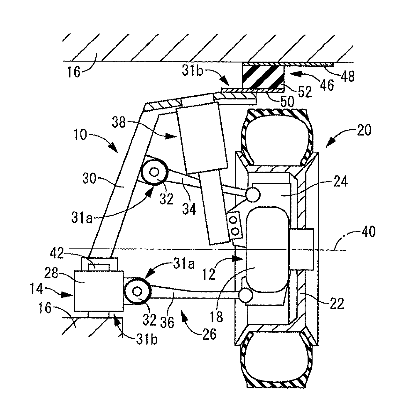
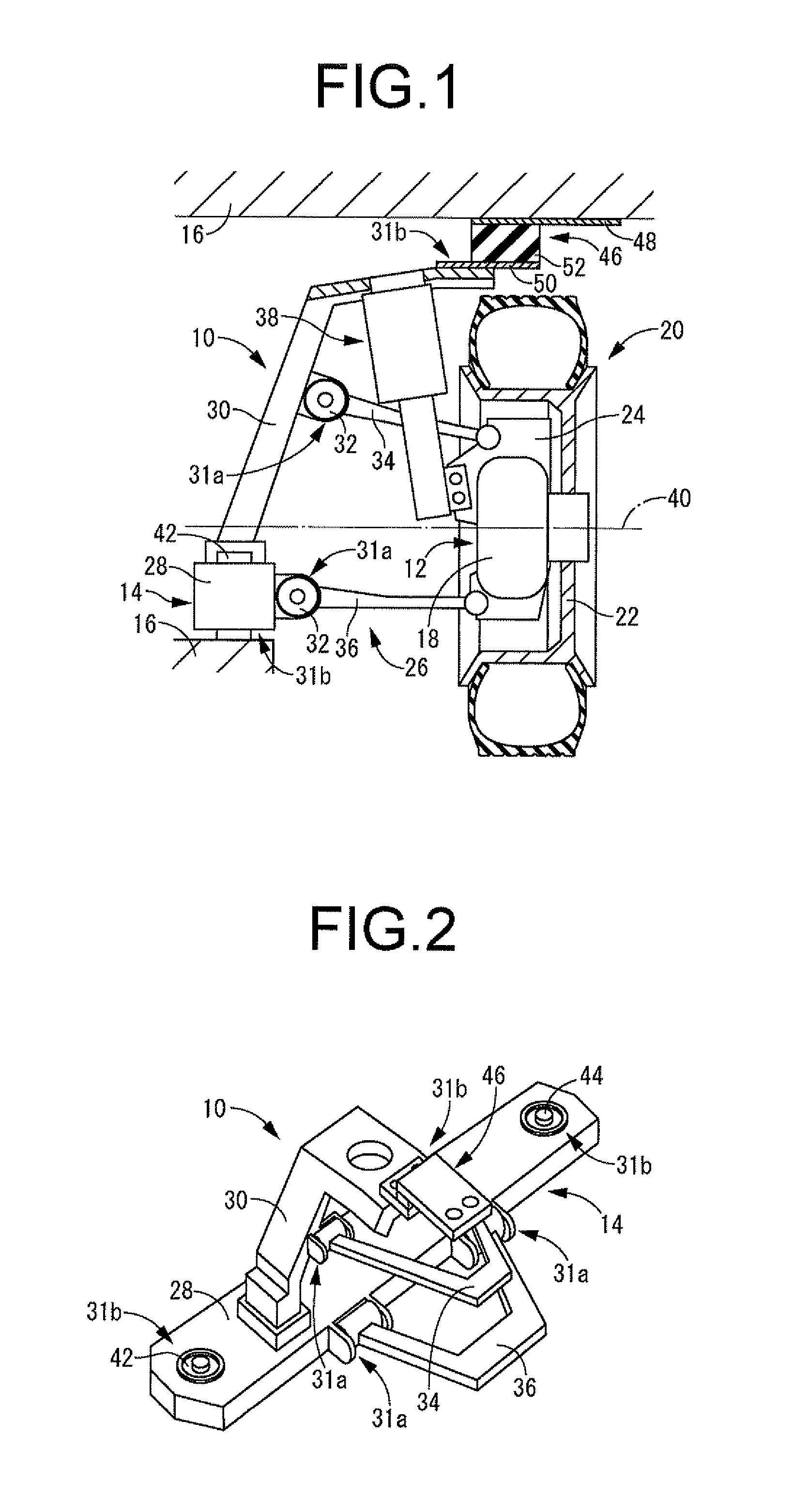
[0032]FIG. 1 depicts as the present invention a drive unit vibration damping support 10 for use in an electric motor-driven vehicle. In this drive unit vibration damping support 10, a drive unit 12 having in-wheel motor construction is supported in vibration damping fashion on a vehicle body 16 via a subframe 14.

[0033]The drive unit 12 configuration includes an electric motor 18 equipped with a shift gear mechanism. The motor housing of this electric motor 18 is disposed accommodated to the inside peripheral side of the rim of a wheel 22 of a wheel assembly 20, and is supported by a wheel assembly support member (a member situated to the wheel knuckle side) 24 to which the brake caliper is attached. The output shaft of the electric motor 18 is linked to the wheel 22 via the shift gear mechanism in the manner taught in JP-A 2006-248417 and JP-A 2005-22554, so that drive power may be transmitted from the electric motor 18 to the wheel assembly 20.

[0034]The wheel assembly support membe...

second embodiment

[0079]The subframe structures and suspension structures, as well as the layout of the drive units herein, are merely exemplary and are not intended to be particularly limiting. Specifically, whereas the drive unit in the second embodiment has a transverse arrangement, the drive unit could instead have a longitudinal arrangement whereby the output shaft is oriented in the vehicle lengthwise direction.

[0080]Further, in the first embodiment, the upper end of the shock absorber 38 or the upper end of a coil spring disposed about the outside thereof may be supported by being attached directly to the vehicle body 16, rather than via the subframe 14. The reason is that it is not an intrinsic function of the shock absorber 38 or the coil spring disposed about the outside thereof to transmit drive torque reaction force.

[0081]The present invention is not limited to application in a drive unit vibration damping support for an electric car, and may be implemented analogously in an electric moto...


PUM


Abstract

A drive unit vibration damping support for use in an electric motor-driven vehicle combines the following structural features. A subframe construction in which a drive unit is supported in vibration damping fashion on a subframe through a first vibration damping device, and the subframe is supported in vibration damping fashion on a vehicle through a second vibration damping device. A total spring constant of the first vibration damping device in a direction of input of torque reaction force of the drive unit is larger than a total spring constant of the second vibration damping device. An average value of a distance between a torque roll axis of the drive unit and the second vibration damping device is greater than an average value of a distance between the torque roll axis and the first vibration damping device.

Description

TECHNICAL FIELD[0001]The present invention relates to a drive unit vibration damping support of novel construction designed to provide vibration damping support of an electric motor unit on a vehicle body in an electric vehicle that employs an electric motor as the drive source.BACKGROUND ART[0002]In view of a recent increase in concerns about the global environment, there have been proposed a number of electric vehicles, such as battery powered vehicles and fuel cell powered vehicles, which rely on an electric motor instead of an internal combustion engine as the drive source.[0003]In the electric vehicles proposed to date, the structure contemplated to replace the conventional power unit that includes an internal combustion engine is simply a modified drive unit that includes a drive motor. Consequently, mounting systems for mounting the drive unit on the vehicle body, such as that disclosed for example in JP-A 7-156663 (Patent Document 1), have retained generally the same constru...

Claims


Application Information

Patent Timeline
IPC IPC(8): B60K7/00F16F15/08B60K1/00
CPCB60G7/02B60G2204/15B60G2300/50B60K1/00F16F15/04B60K2001/001B60K2007/0038B60K2007/0092B62D21/11B60K7/0007
Inventor HAMADA, MASAAKIOHNISHI, MASAHIRO
Owner TOKAI RUBBER IND LTD
Learn More