Consciousness state determination system and autonomous driving apparatus
a technology of consciousness state and determination system, applied in the direction of instruments, transportation and packaging, messaging/mailboxes/announcements, etc., can solve problems such as inattention of drivers
- Summary
- Abstract
- Description
- Claims
- Application Information
AI Technical Summary
Benefits of technology
Problems solved by technology
Method used
Image


Examples
first embodiment
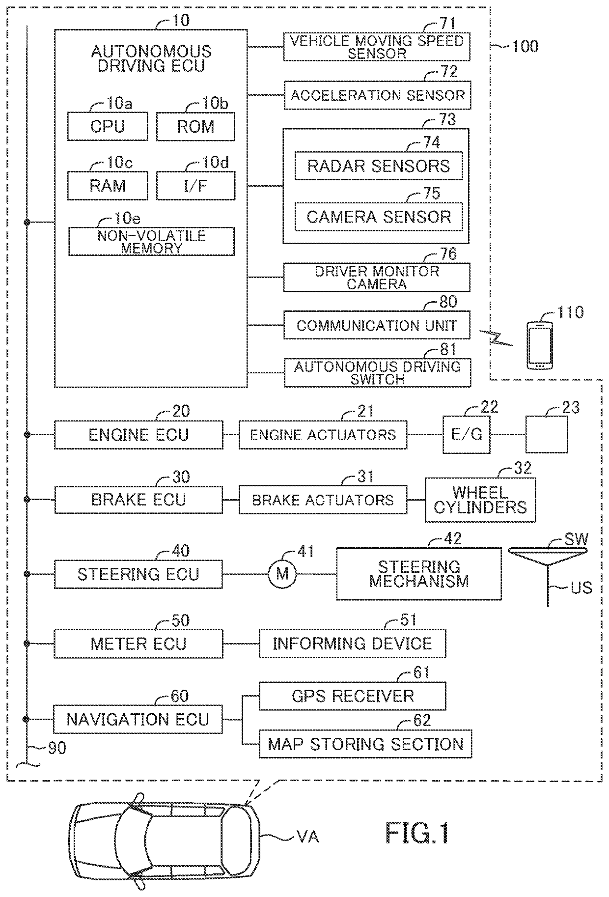
[0034]As shown in FIG. 1, a consciousness state determination system includes an autonomous driving apparatus 100 mounted on or applied to a vehicle VA and a mobile terminal 110.
[0035]
[0036]The autonomous driving apparatus 100 includes an autonomous driving ECU 10, an engine ECU 20, a brake ECU 30, a steering ECU 40, a meter ECU 50, and a navigation ECU 60. The ECUs 10, 20, 30, 40, 50, and 60 are electrically connected to send and receive data to and from each other via a CAN (Controller Area Network) 90.
[0037]ECU stands for electronic control unit. The ECU is an electronic control unit which includes a micro-computer as a main component. The micro-computer includes a CPU, a ROM, a RAM, an interface, and a non-volatile memory. The CPU is configured or programmed to realize various functions by executing instructions, or programs, or routines memorized in the ROM. For example, the autonomous driving ECU 10 includes a micro-computer which includes a CPU 10a, a ROM 10b, a RAM 10c, an i...
operation example
[0107]With reference to FIG. 8, operations of the autonomous driving apparatus 100 (in particular, the ECU 10) and the mobile terminal 110 will be specifically described.
[0108]When the driver DR gets in the vehicle VA, wireless connection between the ECU 10 and the mobile terminal 110 is established. For example, the wireless connection between the ECU 10 and the mobile terminal 110 may be established by paring of Bluetooth (registered trademark). Thereby, the ECU 10 and the mobile terminal 110 start communication via the communication unit 80 (Step 801).
[0109]Then, the driver DR drives the vehicle VA. When the vehicle VA moves on the limited highway at the vehicle moving speed SPD equal to or lower than the predetermined speed threshold SPDth, and the driver DR presses the autonomous driving switch 81, the ECU 10 determines that the predetermined autonomous driving execution condition becomes satisfied and starts executing the autonomous driving control (level 3) (Step 802). Then, ...
second embodiment
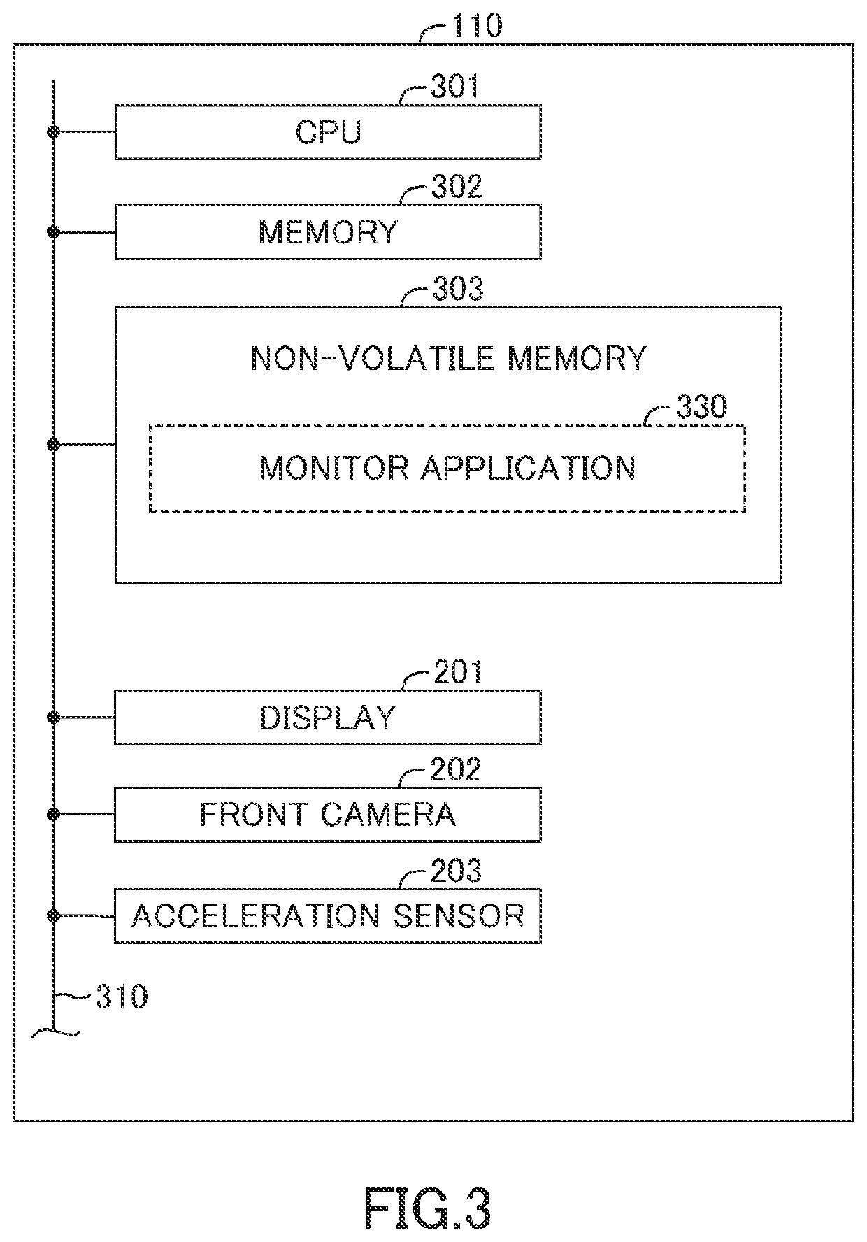
[0130]Next, the consciousness state determination system according to a second embodiment of the present disclosure will be described. In the second embodiment, the monitor application 330 includes a function of detecting operation information. The operation information is information on operations to the mobile terminal 110 carried out by the driver DR. The mobile terminal 110 sends the operation information to the ECU 10 as the terminal-side information.
[0131]In particular, the mobile terminal 110 executes the monitor application 330 and detects a first operation and a second operation described below. In addition, the mobile terminal 110 acquires information on points of time of detecting the operations such as the first operation and the second operation.
[0132]The first operation is an operation as a so-called tapping operation of touching the display 201 with a finger and promptly releasing the finger from the display 201.
[0133]The second operation is an operation as a so-calle...
PUM
 Abstract
Description
Claims
Application Information
 - R&D
- Intellectual Property
- Life Sciences
- Materials
- Tech Scout
- Unparalleled Data Quality
- Higher Quality Content
- 60% Fewer Hallucinations
Browse by: Latest US Patents, China's latest patents, Technical Efficacy Thesaurus, Application Domain, Technology Topic, Popular Technical Reports.
© 2025 PatSnap. All rights reserved.Legal|Privacy policy|Modern Slavery Act Transparency Statement|Sitemap|About US| Contact US: help@patsnap.com