Crusher

a technology of crushing machine and crushing chamber, which is applied in the field of crushing machine, can solve the problems of increasing failure frequency, material throughput falling, and difficulty in achieving the effect of crushing machin

Pending Publication Date: 2022-09-15
WESCONE DISTRIBUTION PTY LTD
View PDF0 Cites 0 Cited by
  • Summary
  • Abstract
  • Description
  • Claims
  • Application Information

AI Technical Summary

Problems solved by technology

As customers have sought lump ore, of a greater particle size, the previously described gyratory crusher has met operational challenges with failures becoming more frequent and material throughput falling.
Indeed, the challenges have risen to the point that customer preference for the previously described crusher is falling and focus on possible substitutes has increased with concern that the gyratory crusher, for example as described in Australian Patent No. 618545 amongst others is fundamentall...

Method used


Image

  • Crusher
  • Crusher
  • Crusher

Examples


Embodiment Construction

[0022]The crushing apparatus of the invention will be better understood in view of the following description of a preferred embodiment thereof made with reference to the accompanying drawings in which:

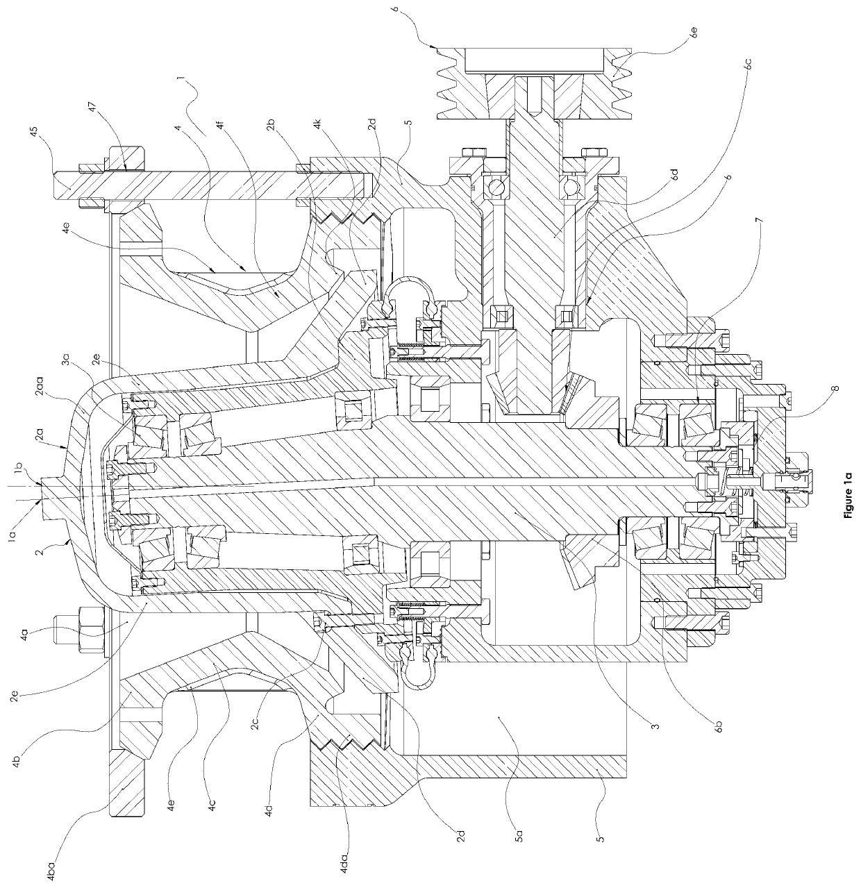
[0023]FIG. 1a is a schematic side section elevation of a prior art gyratory crusher.

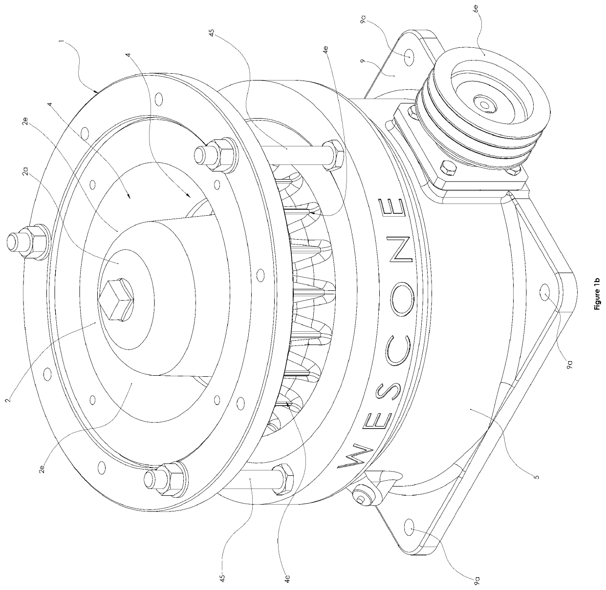
[0024]FIG. 1b is an orthogonal view of the gyratory crusher of FIG. 1a.

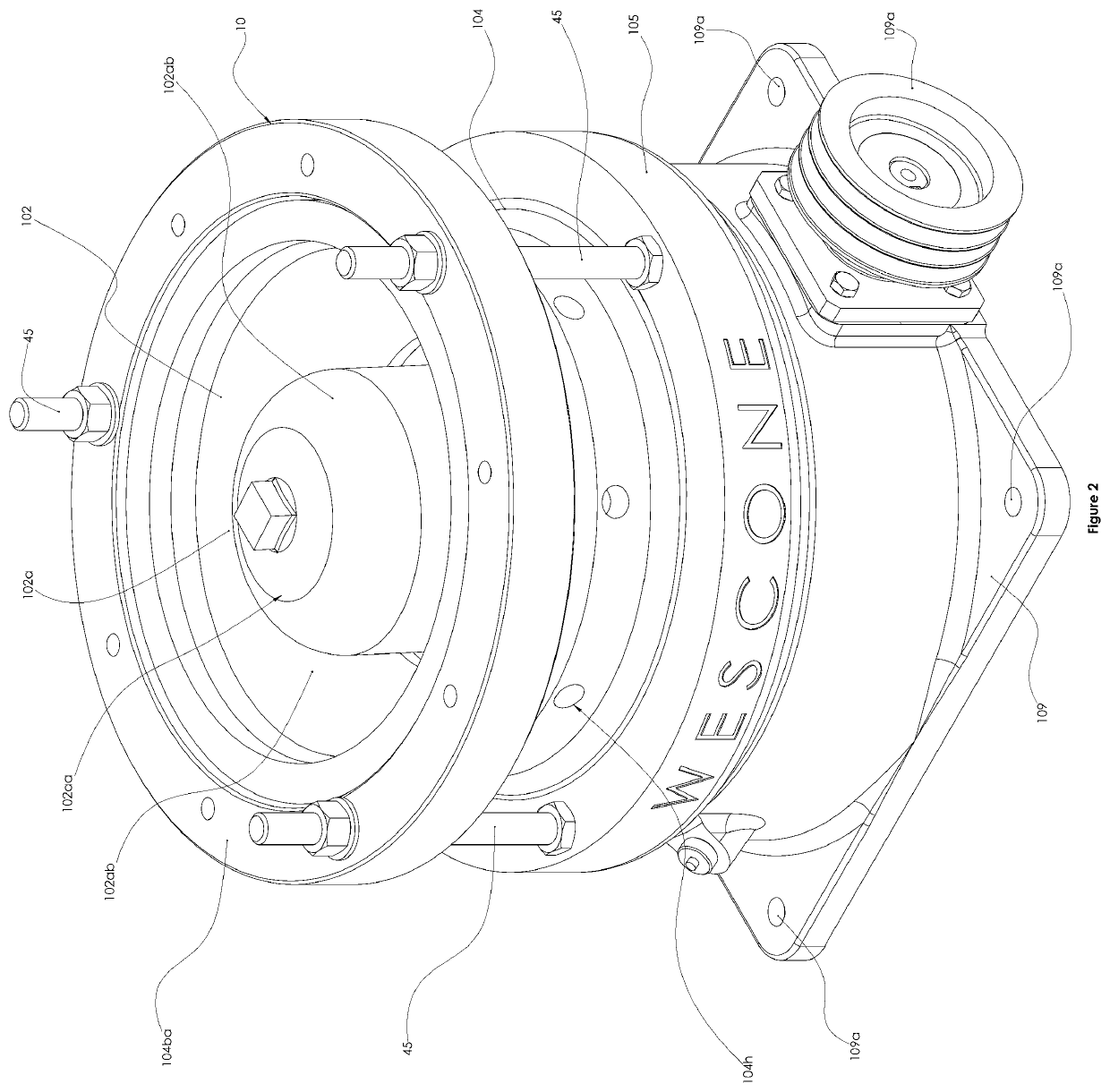
[0025]FIG. 2 is an orthogonal view of a gyratory crusher according to one embodiment of the present invention.

[0026]FIG. 3 is a detailed side section of the gyratory crusher of FIG. 2.

[0027]FIG. 4 is a partial orthogonal view of a crusher being a further embodiment of the crusher of the present invention.

[0028]FIG. 4a is a schematic side section of an upper portion of the crusher showing bowl, feed chute, crushing head and rotating shaft in operative condition.

[0029]FIG. 5 is an orthogonal schematic side section of an upper portion of the crusher showing bowl, feed chute, crushing head and rotating shaft in operative condition.

[0030...


PUM


Abstract

A gyratory crushing apparatus for frangible or friable material comprises: a bowl having a chamber for receiving the material and a discharge opening disposed at the base with a central axis and a gyratory axis extending at an angle to the central axis; a crushing head and a drive assembly. The discharge opening defines a throat with a circumferential wall and the crushing head is disposed within the discharge opening. The crushing head has a crushing face in spaced relation to the circumferential wall of the throat defining a nip between the circumferential wall and the crushing face. The drive assembly includes a transmission and a rotatable eccentric shaft for driving the crushing head within the bowl and about the gyratory axis in a notating motion. The bowl also comprises a feed section and a discharge section, each defined by a wall and spaced by a mid-section, wherein thickness of a wall defining the mid-section is greater than a thickness of the discharge section wall.

Description

FIELD OF THE INVENTION[0001]This invention relates to crushing apparatus for frangible or friable material.BACKGROUND ART[0002]Australian Patent No. 618545 relates to a suspended shaft gyratory crusher comprising a bowl having a chamber for receiving material to be crushed with the bowl having a central discharge opening at its base. A crushing head, with a gyratory axis, is disposed generally centrally within the discharge opening having a crushing space spaced from the wall of a throat to define an annular nip. The crushing head is driven by a drive assembly to permit rotational and oscillatory motion of the crushing head about a pivot point to crush material to a finer particle size.[0003]Crushers of gyratory type have until recently proved successful, for example, in iron ore mining operations. However, market conditions in extractive industries such as iron ore are dynamic and customer demand for ores of various types can change. Iron ore, for example, is available in fine and ...

Claims


Application Information

Patent Timeline
IPC IPC(8): B02C2/04
CPCB02C2/045B02C2/047B02C2/04
Inventor BIONDILLO, JOESUE, AYRTONBOLTON, LEEBERTI, DANIEL
Owner WESCONE DISTRIBUTION PTY LTD
Why Eureka
Try Eureka