
Depolymerization System Having Coil-Wound Heat Exchanger

Pending Publication Date: 2022-09-08
ZHENHAI PETROCHEM JIANAN ENG
View PDF0 Cites 0 Cited by
  • Summary
  • Abstract
  • Description
  • Claims
  • Application Information

AI Technical Summary

Benefits of technology

The present invention provides a depolymerization system with a tube-wound heat exchanger that can increase the rate of depolymerization and prolong the operation of the device.

Problems solved by technology

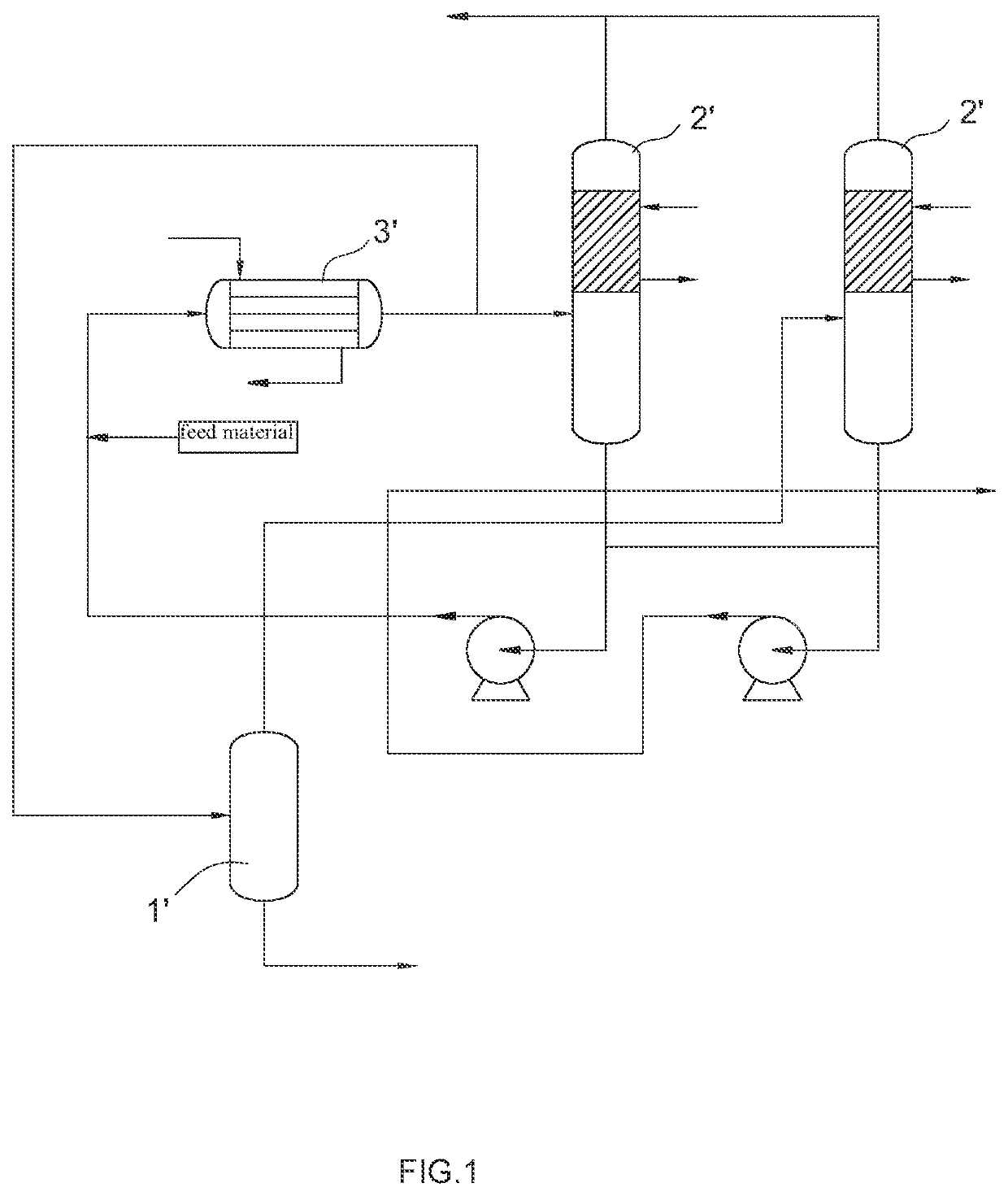
However, the tubular heat exchanger 3′ has low efficiency, low flow velocity, low material outlet temperature and low depolymerization conversion rate.
Since the used heating medium is high in temperature, the wall of the heat exchanger is high in temperature, so that the wall of the heat exchanger is prone to polymerization and coking.
However, in the high-temperature gas-phase depolymerization, CPD and other active components are very easy to implode to form insoluble brown-yellow particles, resulting in the blockage of the heat exchanger.
Therefore, this gas-phase depolymerization requires a very short retention time.
Thus, in this application, since the tubular heat exchanger is used and the used heating medium is high in temperature, it is very easy to block the heat exchanger by polymerization, thereby affecting the operation period of the whole device.
Moreover, the technological process adopted in this application is relatively complicated.

Method used


Image

  • Depolymerization System Having Coil-Wound Heat Exchanger
  • Depolymerization System Having Coil-Wound Heat Exchanger
  • Depolymerization System Having Coil-Wound Heat Exchanger

Examples


embodiment 1

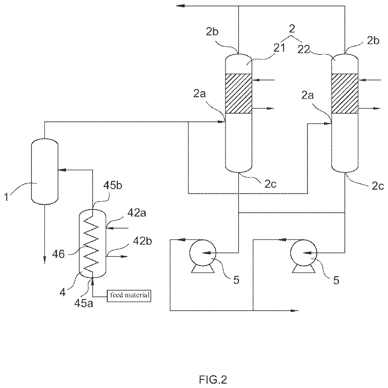
[0030]FIGS. 2-7 show a first preferred embodiment of a depolymerization system with a tube-wound heat exchanger according to the present invention. The depolymerization system comprises a heat exchange device for heating a material, having a material output; a gas-liquid separation device 1 having an inlet and a gas output, connected to the material output of the heat exchange device; and a depolymerization device 2 connected to the gas output of the gas-liquid separation device 1; the heat exchange device comprises at least one tube-wound heat exchanger 4.

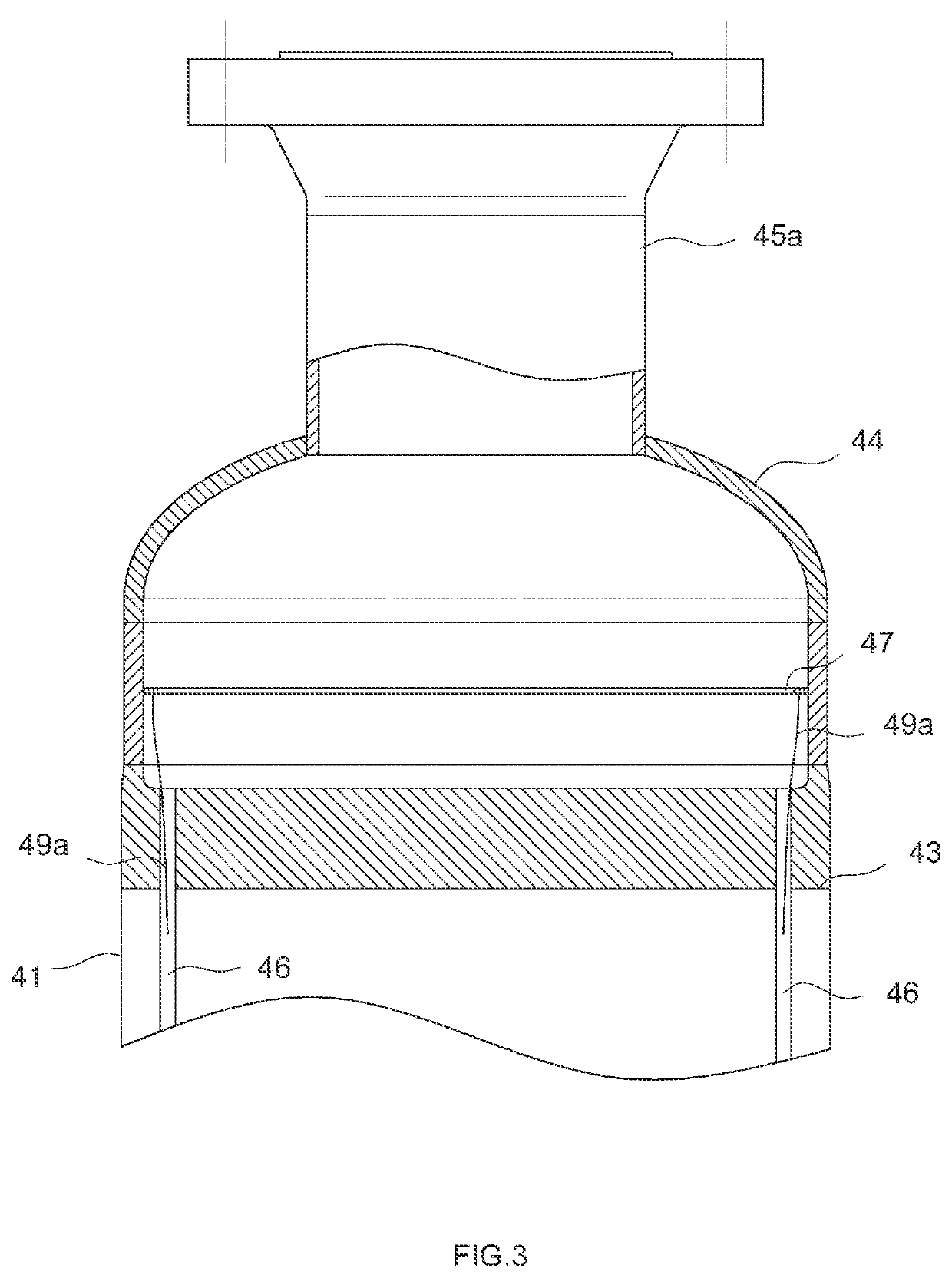
[0031]Each tube-wound heat exchanger 4 comprises: a shell-pass cylinder 41 having two ends; a first shell-pass connecting tube 42a and a second shell-pass connecting tube 42b both connected to the shell-pass cylinder 41; a first tube plate 43 and a second tube plate both attached to the two ends of the shell-pass cylinder 41; a first tube box 44 having a tube-pass inlet connecting tube 45a disposed on the first tube plate 43; a se...

embodiment 2

[0041]FIG. 8 shows a second preferred embodiment of the depolymerization system according to the present invention. The depolymerization system is basically the same as that in Embodiment 1, the only difference is that the heat exchange device comprises at least two tube-wound heat exchangers 4 and the tube passages of the tube-wound heat exchangers 4 are connected in series or in parallel to each other, specifically:

[0042]The heat exchange device comprises a first tube-wound heat exchanger 401, a second tube-wound heat exchanger 402, and a third tube-wound heat exchanger 403; the tube passage of the first tube-wound heat exchanger 401 is connected in parallel to the tube passage of the second tube-wound heat exchanger 402, and the tube passage of the first tube-wound heat exchanger 401 and the tube passage of the second tube-wound heat exchanger 402 both receive the material and are connected to the inlet of the gas-liquid separation device 1; the tube passage of the third tube-wou...

embodiment 3

[0044]FIG. 9 shows a third preferred embodiment of the depolymerization system according to the present invention. The depolymerization system is basically the same as that in Embodiment 1, the only difference is that, the heat exchange device in this embodiment further comprises a tubular heat exchanger 3 (having the same structure as the tubular heat exchanger in the prior art) having a tube passage for the material to pass through and a shell passage for a second heating medium to flow through; the tube passage of the tubular heat exchanger 3 is connected in series to the tube passage of the tube-wound heat exchanger 4, and the tube-pass inlet connecting tube 45a of the tube-wound heat exchanger 4 receives the material from the tube passage of the tubular heat exchanger 3. In this way, the material firstly enters the tube passage of the tubular heat exchanger 3 for primary heating, and then enters the tube passage of the tube-wound heat exchanger 4 for secondary heating.

[0045]Of ...


PUM


Abstract

A depolymerization system with a tube-wound heat exchanger (4) comprises a heat exchange device for heating a material, having a material output; a gas-liquid separation device (1) having an inlet and a gas output, connected to the material output of the heat exchange device; and a depolymerization device (2) connected to the gas output of the gas-liquid separation device (1); the heat exchange device comprises at least one tube-wound heat exchanger (4). The depolymerization rate is greatly improved and the service period of the whole depolymerization system can be greatly improved.

Description

TECHNICAL FIELD OF THE INVENTION[0001]The present invention belongs to the technical field of chemical equipment, and particularly relates to a depolymerization system with a tube-wound heat exchanger.BACKGROUND OF THE INVENTION[0002]The conventional depolymerization system mostly comprises an ordinary heat exchanger and a depolymerization device. As shown in FIG. 1, the ordinary heat exchanger is mostly a tubular heat exchanger 3′, and the material is heated by the tubular heat exchanger 3′ and then enters the depolymerization device 2′ for depolymerization. However, the tubular heat exchanger 3′ has low efficiency, low flow velocity, low material outlet temperature and low depolymerization conversion rate. For a material prone to depolymerization and polymerization, generally due to the low efficiency of the ordinary heat exchanger, circulating oil (generally a component from the bottom of the depolymerization device) can be added to the fresh material as a feed material, and only...

Claims


Application Information

Patent Timeline
IPC IPC(8): B01J19/00F28D7/02B01J19/24
CPCB01J19/0013F28D7/02B01J19/24F28D2021/0022F28D7/00B01J2219/00103F28D7/024F28F9/027Y02W30/62B01J2219/00083B01J2219/00081
Inventor TAO, JIANGZHANG, XIANANWANG, JIANLIANGHU, XINGMIAOWANG, LIWU, LIJUNHUANG, CHENYANG
Owner ZHENHAI PETROCHEM JIANAN ENG
Learn More