
Process for converting inferior feedstock oil

a technology of feedstock oil and conversion process, which is applied in the direction of hydrocarbon oil cracking hydrocarbon oil treatment products, etc., can solve the problems of increasing the reducing the chemical hydrogen consumption, and increasing the liquid product yield. , to achieve the effect of high liquid product yield, low chemical hydrogen consumption, and increased run length of the hydrotreating uni

Active Publication Date: 2022-06-21
CHINA PETROCHEMICAL CORP +1
View PDF11 Cites 0 Cited by
  • Summary
  • Abstract
  • Description
  • Claims
  • Application Information

AI Technical Summary

Benefits of technology

This process significantly extends the operation period of the hydrogenation unit, reduces chemical hydrogen consumption, and increases liquid product yield while maintaining the quality of hydrogenated residual oil.

Problems solved by technology

There is still a need for the new converting process of inferior feedstock oil, which process can increase the run length of hydrotreating unit, reduce the chemical hydrogen consumption, and increase the liquid product yield.

Method used


Image

  • Process for converting inferior feedstock oil

Examples


example 1

[0126]Example 1 provided an adjustable low severity hydrogenation reaction according to the present invention. The reaction temperature and the liquid hourly space velocity were adjusted along with the reaction time in stages, and the hydrogen / oil volume ratio and the hydrogen partial pressure were maintained at 800 normal m3 / m3 and 15 MPa respectively. For the hydrogenated product of the inferior feedstock oil, the cutting point of hydrogenated residual oil was set at 350° C.

[0127]The hydrogenation test was conducted in a continuous high-pressure fixed-bed pilot device, which comprised three reactors connected in series, each containing a hydrogenation protecting catalyst (RG-10A), a hydrodemetallization catalyst (RDM-2B), and a hydrodesulfurization catalyst (RMS-1B) in a volume ratio of 5:45:50. At the time of the test, the pilot device was in its initial operation and its operating time was less than 50 hours.

[0128]The catalytic cracking test was conducted in a middle-size FCC de...

example 2

[0132]The reaction product obtained from the 5000th-5500th hour of the reaction of Example 1 (see Table 3) was selected as the object in the subsequent study. The hydrogenated residual oil was used as the feedstock of the first catalytic cracking reaction. The hydrogenated residual oil was subjected to the first catalytic cracking reaction and the separation and fractionation to produce the first dry gas, the first LPG the first gasoline, the first diesel and the first FGO. The cutting point of the first FGO was set at 330° C., and comprised 33.23 wt % of the feedstock. The first FGO was sent to the FGO hydrogenation unit, the resultant product was subjected to a gas-liquid separation. The hydrogenated gas oil as the liquid stream was subjected to the second catalytic cracking reaction to produce the second dry gas, the second LPG the second gasoline, the second diesel and the second FGO. The second FGO was sent to the FGO hydrogenation unit. The operation conditions were listed in ...


PUM

PropertyMeasurementUnit
densityaaaaaaaaaa
densityaaaaaaaaaa
reaction temperatureaaaaaaaaaa

Abstract

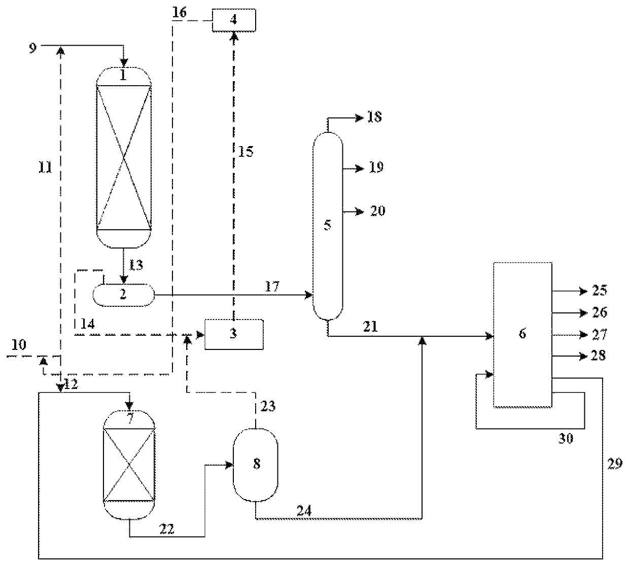
A process for converting inferior feedstock oil includes several steps. In step a) the inferior feedstock oil is subjected to a low severity hydrogenation reaction. The reaction product is separated to produce a gas, a hydrogenated naphtha, a hydrogenated diesel and a hydrogenated residual oil. In step b) the hydrogenated residual oil obtained in step a) is subjected to a first catalytic cracking reaction, the reaction product is separated to produce a first dry gas, a first LPG, a first gasoline, a first diesel and a first FCC-gas oil. In step c) the first FCC-gas oil obtained in step b) is subjected to a hydrogenation reaction of gas oil, the reaction product is separated to produce a hydrogenated gas oil, and in step d) the hydrogenated gas oil obtained in step c) is subjected to the first catalytic cracking reaction of step b) or a second catalytic cracking reaction.

Description

FIELD OF THE INVENTION[0001]The present invention relates to a process for converting inferior feedstock oil.BACKGROUND OF THE INVENTION[0002]CN101210200B discloses a combination of residual oil hydrogenation and catalytic cracking. Residual oil, FCC heavy cycle oil with solid impurities being removed, optionally fractioned oils and optionally FCC slurry distillate are together sent to a residual oil hydrogenation unit, the resultant hydrogenated residual oil and optionally vacuum gas oil are sent to a FCC unit to produce various products; the FCC heavy cycle oil, after removing the solid impurities, can be recycled to the residual oil hydrogenation unit; the FCC slurry is subjected to distillation and the resultant distillate can be recycled to the residual oil hydrogenation unit.[0003]CN102344829A discloses a combination of residual oil hydrogenation, FCC heavy oil hydrogenation and catalytic cracking. The liquid stream obtained from the residual oil hydrogenation reactor is disti...

Claims


Application Information

Patent Timeline
Patent Type & Authority Patents(United States)
IPC IPC(8): C10G69/00C10G69/04C10G65/10C10G47/02
CPCC10G69/04C10G47/02C10G65/10C10G2300/107C10G2300/1077C10G2300/205C10G2400/02C10G2400/04C10G2400/26C10G11/02C10G65/12
Inventor XU, YOUHAOLIU, TAOWANG, XINDAI, LISHUNLAN, TIANNIE, HONGLI, DADONG
Owner CHINA PETROCHEMICAL CORP
Learn More