
Method and apparatus for performing electroretinography, including enhanced electrode

a technology of electroretinography and electrodes, applied in the field of electroretinography methods and electrodes, can solve the problems of significant confounding factor, no valid test being recorded, wasted time by test subjects, technicians, clinicians,

Pending Publication Date: 2022-09-08
DIAGNOSYS LLC
View PDF0 Cites 0 Cited by
  • Summary
  • Abstract
  • Description
  • Claims
  • Application Information

AI Technical Summary

Benefits of technology

The invention provides a new and better electrode for testing the eye using a DTL style. It includes a bipolar electrode, a conductive thread to measure only a select part of the eye, and sticky pads to hold the electrode in place. This allows for more accurate placement of the electrode relative to the eye.

Problems solved by technology

By way of example but not limitation, such artifacts may include electrical noise (i.e., electromagnetic interference) that comes from other machines in the area around the testing equipment (which artifacts typically oscillate at the frequency of the electrical main power supply used in the region of the world where the test equipment is situated, typically 50 or 60 hz cyclical noise).
This is a significant confounding factor in correctly measuring the ERG retinal response of a test subject.
Artifact signals can overlap in time and frequency space, and are therefore a significant confounding factor to conducting an accurate ERG measurement of retinal function of a test subject.
In some cases, clinicians recognize the presence of eye muscle artifacts in a test and discard the test altogether, resulting in wasted time by the test subject, technician, and clinician, with no valid test being recorded.
In other cases, the clinician does not recognize the presence of artifacts in a test, resulting in a strong possibility of an incorrect interpretation and, in the worst case, an incorrect diagnosis of disease or health.
Except for very highly trained test subjects, these types of muscle artifacts are unavoidable during the test, even when the subject tries their very best to avoid generating them.
Unfortunately, although a DTL electrode having a conductive thread disposed on the apex of the cornea yields the largest active signal, such placement is also the least comfortable for the test subject.
Thus, the challenge is to balance signal strength with test subject comfort.
However, since contact lens electrodes hold the eye open to prevent blinking, many test subjects may find them uncomfortable or intimidating.
Prolonged recordings utilizing contact lens electrodes tend to increase the risk of corneal abrasions, conjunctival abrasions, and irritation from the lens moving against the cornea.
Notably, the contact lens electrode adds a layer of material atop the cornea, which alters a patient's refraction.
Therefore, contact lens electrodes are not suitable for use for pattern ERG (PERG) tests.
It is smaller and slightly more comfortable for the test subject to wear than the Burian Allen contact lens electrode, but the Jet electrode is less secure on the eye and can be more easily blinked out by the test subject.
Although reusable, sterilizing gold foil electrodes can be challenging, and there is disagreement among researchers about whether electrodes reused more than three times produce decreased amplitudes.
However, one significant limitation of DTL electrodes is that DTL electrodes are currently only available as monopolar active electrodes, with no option for combined active-plus-reference bipolar electrodes (with or without also incorporating a ground electrode).
Another limitation of current DTL electrodes is that the active measurement surface (i.e., the conductive silver coated thread(s) of the DTL electrode) spans a large range across the eye, thereby causing the measured signal to come from a large, averaged surface area, across the entire eye.
A further limitation of DTL electrodes has been the lack of different options for the shape of the pads which hold the conductive thread of the DTL electrode in place, thereby limiting options for accurate placement of the thread on the eye.

Method used


Image

  • Method and apparatus for performing electroretinography, including enhanced electrode
  • Method and apparatus for performing electroretinography, including enhanced electrode
  • Method and apparatus for performing electroretinography, including enhanced electrode

Examples


Embodiment Construction

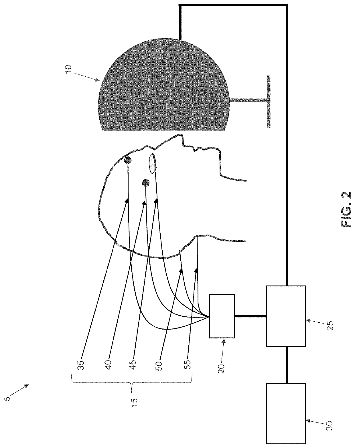
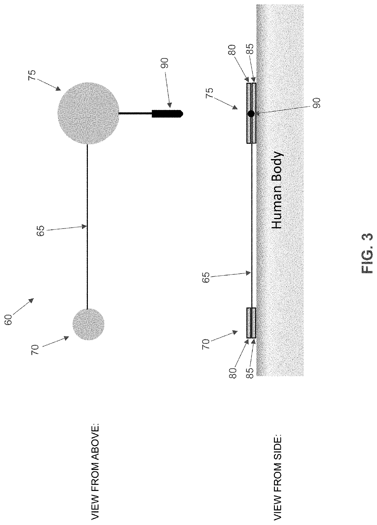
[0083]The present invention comprises the provision and use of a new and improved DTL-style electrode comprising (i) a bipolar electrode, (ii) a conductive thread configured to measure the electrical response of only a select portion of the region of the eye contacted by the conductive thread, and / or (iii) sticky pads for mounting the novel electrode in place which permit a wider range of options for accurate placement of the electrode relative to the test subject's eye.

[0084]More particularly, the present invention can be characterized by reference to three novel aspects that can be used independently of one another, or in combination with one another, in order to improve the performance, inter-session repeatability, and cost effectiveness of performing ERG tests when compared against use of a traditional DTL electrode.

[0085]To summarize, the first novel aspect of the present invention comprises the provision and use of an electrode comprising a thin coating of non-conductive mater...


PUM


Abstract

Apparatus for use in performing electroretinography on a test subject, the apparatus comprising: at least one electrically conductive thread, the at least one electrically conductive thread comprising a first end and a second end, wherein the first end of the at least one electrically conductive thread is configured to mount to skin on one side of an eye of the test subject and the second end is configured to mount to skin on the opposite side of the eye of the test subject, such that the at least one electrically conductive thread is in contact with a surface film of an eye; and an electrically non-conductive coating applied to at least one region of the at least one electrically conductive thread, whereby to electrically isolate the at least one region of the at least one electrically conductive thread from the eye.

Description

REFERENCE TO PENDING PRIOR PATENT APPLICATION[0001]This patent application claims benefit of pending prior U.S. Provisional Patent Application Ser. No. 63 / 157,272, filed Mar. 5, 2021 by Diagnosys LLC and Jeffrey D. Farmer et al. for ENHANCED DTL ELECTRODE (Attorney's Docket No. DIAGNOSYS-14 PROV).[0002]The above-identified patent application is hereby incorporated herein by reference.FIELD OF THE INVENTION[0003]This invention relates to ophthalmic psychophysical diagnostic equipment in general, and more particularly to new and improved methods and electrodes for performing electroretinography.BACKGROUND OF THE INVENTION[0004]Ophthalmic electrophysiology diagnostic equipment, such as that manufactured and sold by Diagnosys LLC of Lowell, Mass., is typically used to stimulate the eye of a test subject using flashes (or moving patterns) of light, and then to measure the resulting electrical response generated at the retina of the test subject (i.e., to obtain an electroretinogram, or “...

Claims


Application Information

Patent Timeline
IPC IPC(8): A61B5/398G01N27/30A61B5/257A61B5/268A61B5/27A61B5/273
CPCA61B5/398G01N27/30A61B5/257A61B5/268A61B5/27A61B5/273A61B2562/043A61B2562/14A61B2562/222A61B5/315A61B5/6814A61B5/6832A61B2562/227
Inventor FARMER, JEFFREY D.DORAN, BRUCEROBSON, RICHARD
Owner DIAGNOSYS LLC
Learn More