Management apparatus for energy storage device, energy storage apparatus, and input/output control method for energy storage device

Pending Publication Date: 2022-08-25
GS YUASA INT LTD
View PDF0 Cites 0 Cited by
  • Summary
  • Abstract
  • Description
  • Claims
  • Application Information

AI Technical Summary

Benefits of technology

The patent text describes a way to prevent a reduction in battery output caused by increased resistance in the battery. This method improves the performance of batteries.

Problems solved by technology

However, conditions under which the diffusion limitation occurs have not been studied sufficiently, in other words, the performance of the battery has not been used sufficiently.

Method used


Image

  • Management apparatus for energy storage device, energy storage apparatus, and input/output control method for energy storage device
  • Management apparatus for energy storage device, energy storage apparatus, and input/output control method for energy storage device
  • Management apparatus for energy storage device, energy storage apparatus, and input/output control method for energy storage device

Examples


embodiment

Details of Embodiment

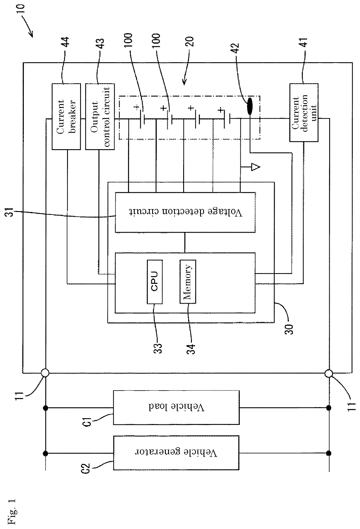
[0043]Hereinafter, an embodiment of the present invention will be described with reference to FIGS. 1 to 21.

[0044]The energy storage apparatus is, for example, an energy storage apparatus 10 that is mounted on an electric vehicle, or a hybrid vehicle driven by an engine and a motor, and the energy storage apparatus supplies power to a vehicle load C1 mounted on the vehicle and is charged by a vehicle generator (e.g., an alternator) C2.

[0045]As illustrated in FIG. 1, the energy storage apparatus 10 includes an assembled battery 20 in which a plurality of energy storage devices 100 are connected in series, a battery management apparatus (an example of an “electrical quantity calculation unit” and a “control unit”, hereinafter referred to as a “battery management unit (BMU)”) 30 that manages the assembled battery 20, a current detection unit (an example of a “measurement unit”) 41, a temperature measurement unit (an example of a “measurement unit”) 42, an output co...

second embodiment

[0098]Next, a second embodiment will be described with reference to FIG. 19.

[0099]Unlike the first embodiment, the input / output control processing of the second embodiment performs output reduction during charge and discharge before comparing the upper limit ΔSOC with the ΔSOC to extend the time until the ΔSOC reaches the upper limit ΔSOC. The description of configurations, operations, and effects common to those of the first embodiment is omitted because it would be a repeated description, and the same reference numerals are used for the same configurations as those of the first embodiment.

[0100]In the output control processing of the second embodiment, first, the CPU 33 gives a command to the voltage detection circuit 31 to detect an open-circuit voltage (OCV) flowing through the assembled battery 20 immediately before the turning-on of the ignition of the vehicle and obtains an initial SOC value from the OCV-SOC correspondence relationship stored in the memory 34 based on the det...


PUM


Abstract

The present invention comprises a voltage detection circuit for measuring the voltage of an assembled battery 20 in which power storage elements 100 are serially connected, a current detection resistor for detecting the current in the assembled battery 20, and a CPU 33 for calculating, inter alia, the amount of energization electricity from continuous charging or continuous discharging of the assembled battery 20. The CPU 33 controls input / output for when the assembled battery 20 is charged / discharged so that ΔSOC, which is the value obtained by dividing the amount of energization electricity by the actual capacity of the assembled battery 20, does not exceed an upper limit ΔSOC.

Description

CROSS REFERENCE TO RELATED APPLICATIONS[0001]This application is a national stage application, filed under 35 U.S.C. § 371, of International Application No. PCT / JP2020 / 032369, filed Aug. 27, 2020, which claims priority to Japan Application No. 2019-158285, filed Aug. 30, 2019, the contents of both of which as are hereby incorporated by reference in their entirety.BACKGROUNDTechnical Field[0002]The present invention relates to a management apparatus for an energy storage device, an energy storage apparatus, and an input / output control method for an energy storage device.Description of Related Art[0003]In a lithium ion battery, it is conventionally known that a phenomenon called a diffusion limitation occurs when a continuous charge-discharge time exceeds a certain time. Therefore, Patent Document JP-A-2006-338944 discloses that when it is detected that the increase amount of the internal resistance of the battery exceeds a predetermined value, the output of the battery is controlled ...

Claims


Application Information

Patent Timeline
IPC IPC(8): H02J7/00H01M10/48G01R31/3842
CPCH02J7/0049H01M10/482G01R31/3842H02J7/007184H02J7/007194H02J7/0048B60L50/64B60L58/13B60L3/04B60L2240/545H01M2010/4271H01M10/425H01M2010/4278H01M10/441
Inventor MATSUI, HIROKIKASHIWA, YUTAOCHIAI, SEIJIRO
Owner GS YUASA INT LTD
Why Eureka
Try Eureka