
Method and system for storing and/or transporting temperature-sensitive materials

a technology of temperature-sensitive materials and methods, applied in the direction of lighting and heating apparatus, packaging goods, domestic cooling apparatus, etc., can solve the problems of inability to meet the requirements of use,

Pending Publication Date: 2022-08-25
COLD CHAIN TECH
View PDF0 Cites 2 Cited by
  • Summary
  • Abstract
  • Description
  • Claims
  • Application Information

AI Technical Summary

Benefits of technology

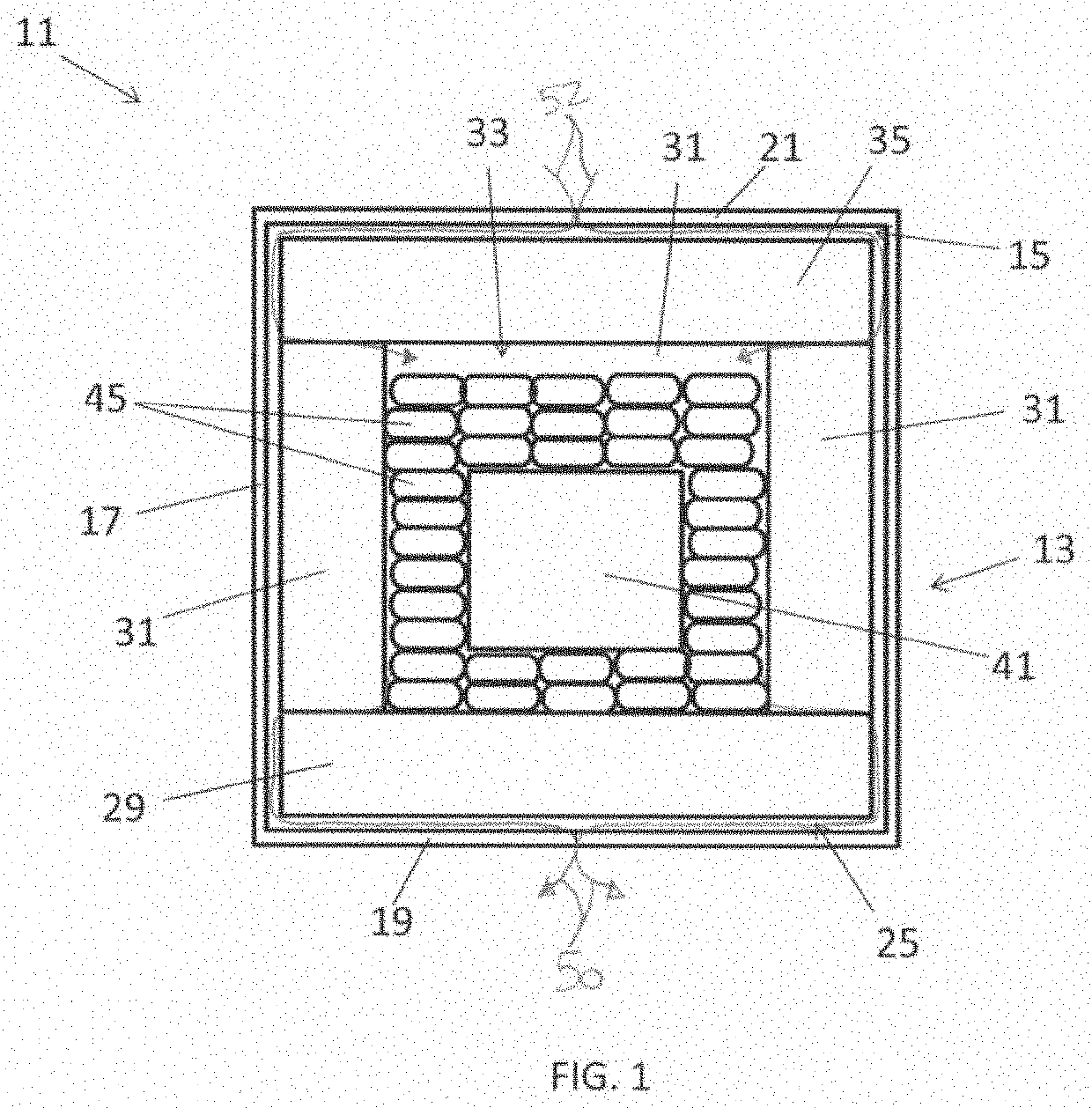
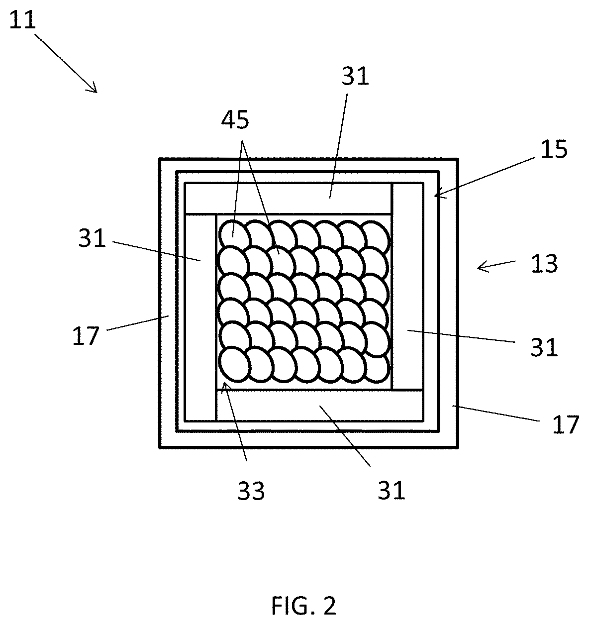
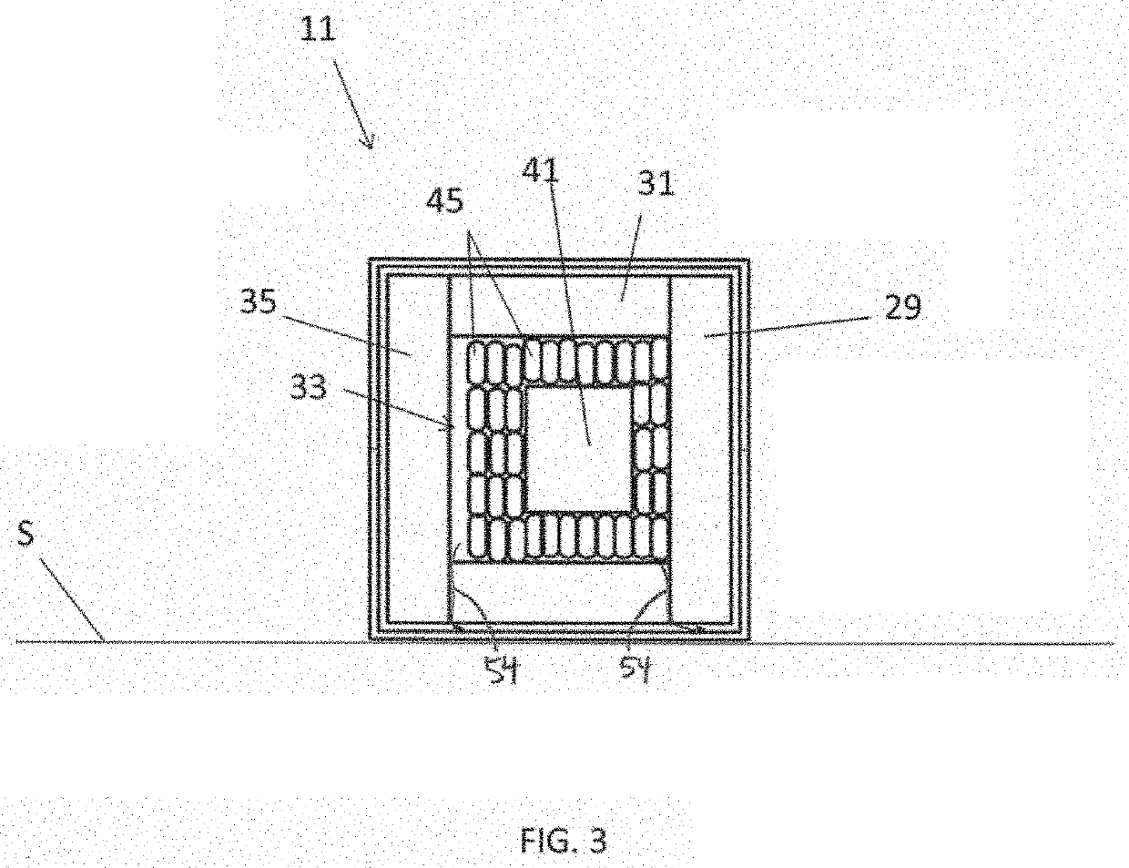
The present invention provides a system for storing and transporting temperature-sensitive materials. The system includes an insulation base and an outer box with a gas flow director. The insulation base has a cavity for holding the temperature-sensitive materials and is connected to the outer box. The gas flow director is placed inside the outer box and is designed to reduce the escape of gas from the insulation base through the interfaces. The technical effects of this system include minimal parts, easy manufacturing, and easy use.

Problems solved by technology

However, as can be appreciated, active temperature-control devices add considerable expense to transportation and / or storage costs.
Those who design and use passive thermal systems often assume that passive temperature-control systems that rely on dry ice are able to consistently maintain an internal temperature that is at the dry ice sublimation temperature of −78° C. In practice, however, this is often not the case.
The aforementioned phenomenon of accelerated sublimation resulting in container temperatures lower than the phase transition temperature is sometimes referred to herein as “supercooling.” As will become apparent below, supercooling may be undesirable if it results in a payload being exposed to a temperature that is lower than the minimum temperature to which the payload should be exposed.
The accelerated loss of dry ice associated with supercooling may also undesirably shorten the duration at which the passive thermal system may maintain the payload within the desired temperature range.
This often results in a temperature gradient within the container, with the bottom of the container being at temperatures of −78° C. or less and with the top of the container being at temperatures much warmer than −78° C. As can be appreciated, such a temperature gradient within the container may be undesirable as different portions of the payload may be exposed to different temperatures, some of which may be outside the desired temperature range.
For example, certain COVID-19 vaccines require storage at temperatures that are no less than −80° C. and that are no greater than −60° C. Unfortunately, however, for at least some of the reasons discussed above, many dry ice passive thermal systems often experience temperatures below −80° C., which is unsuitable for articles like the aforementioned COVID-19 vaccine, which should not be exposed to temperatures below −80° C. In fact, as noted by Mei, it is not uncommon for temperatures to be as low as −85° C. in many dry ice passive thermal systems, rendering such systems unsuitable for the foregoing COVID-19 vaccine.
As can be appreciated, such low temperatures are unsuitable for many articles like the above-noted COVID-19 vaccine.

Method used


Image

  • Method and system for storing and/or transporting temperature-sensitive materials
  • Method and system for storing and/or transporting temperature-sensitive materials
  • Method and system for storing and/or transporting temperature-sensitive materials

Examples


example 1

ve

[0132]A shipper was used that includes an outer corrugate box of cubic geometry with external dimensions 13 11 / 16 inches×13 11 / 16 inches×12 11 / 16 inches. Into this box was inserted a riser and a 5-piece bottom vacuum insulated panel (VIP) assembly that includes 4 VIPs, each 11.75 inches wide×9 inches tall×1 inch thick arranged in a pinwheeled fashion and strapped together on top of a fifth VIP of dimensions 12.75 inches long×12.75 inches wide×1 inch thick, which serves as a base. One sheet of chipboard, cut into a cross shape, was inserted inside the 5-piece bottom assembly so that all 5 sides of the interior were covered by the chipboard. On top of the chipboard, two lengths of plastic sheet, pre-shaped to conform to the internal contour of the VIP assembly were arranged at right angles to each other inside the cavity created by the VIP assembly, thereby creating a rigid inner lining. A sixth VIP of the same dimensions as the fifth VIP was encased in a rigid plastic case and was ...

example 2

as Flow

[0135]A shipping system similar to that of Example 1 was prepared as above, except that a gas flow director was placed inside the outer corrugate box prior to inserting the 5-piece bottom VIP assembly. The intention was to reduce gas flow through the gaps between the 5 VIPs making up the VIP assembly by providing a non-airtight barrier external to the VIP assembly. The gas flow director was prepared by taking a large plastic trash bag (24″×32″ 0.9 mil 12-16 gal LLDPE black CLEAN CHOICE® can liner part number 0606222 from Fastenal Company (Winona, Minn.), and cutting the top portion off so that the film material only extended up the side walls and did not extend as far as the seam between the lid and VIP assembly. Like the shipper of Example 1, the shipper of Example 2 had a dry ice open area of 10.75 inches×10.75 inches. After closing the lid and taping the top flaps of the outer corrugate box, the entire shipper weighed 30.90 lbs. The shipper was maintained in an upright ori...

example 3

as Flow Directed Through Single Central Vent

[0136]A shipping system similar to that of Examples 1 and 2 was prepared as above, except that the plastic bag was cut less severely so that it extended above the side walls. After filling the shipper with dry ice, the extra plastic material was folded over the side walls and duct-taped so that only a small vent hole was left uncovered near the center of the top face. The intention was not only to restrict the gas flow through the gaps between the 5 VIPs making up the VIP assembly by providing a non-airtight barrier, but also to direct gas flow through a single central vent underneath the sixth VIP. After closing the lid and taping the top flaps of the outer corrugate box, the entire shipper weighed 34.38 lbs. The shipper was maintained in an upright orientation with its lid at the top for 1.5 hours, then tipped onto its side for an additional 19.5 hours. The shipper was re-weighed after 21 hours. Then, it was tipped again so that the ship...


PUM


Abstract

Method and system for storing and / or transporting temperature-sensitive materials. In one embodiment, the system is designed for use as a dry ice shipper and includes an outer box, a vacuum insulated panel (VIP) base assembly, a VIP lid assembly, and a gas flow director. The VIP base assembly is positioned within the outer box and includes five VIPs arranged to form a container having a bottom, four sides, and an open top. The VIP lid assembly, which may be coupled to a top closure flap of the outer box, includes a VIP dimensioned to close the open top of the VIP base assembly. The gas flow director, which may comprise a bag having an opening at its top end, may be positioned within the outer box and may be used to receive the VIP base assembly. The gas flow director inhibits convective gas flow that promotes excessive dry ice sublimation.

Description

CROSS-REFERENCE TO RELATED APPLICATIONS[0001]The present application claims the benefit under 35 U.S.C. 119(e) of U.S. Provisional Patent Application No. 63 / 151,146, inventors Heather M. Conway et al., filed Feb. 19, 2021, the disclosure of which is incorporated herein by reference.BACKGROUND OF THE INVENTION[0002]The present invention relates generally to methods and systems for storing and / or transporting temperature-sensitive materials and relates more particularly to a novel method and system for storing and / or transporting temperature-sensitive materials.[0003]Various articles of commerce, such as, but not limited to, many types of pharmaceuticals, biological materials, medical devices, foods, and beverages, must be maintained within a desired temperature range during transportation and / or storage in order to prevent spoilage. One way in which such temperature maintenance may be achieved is by transporting and / or storing such articles or materials inside an active temperature-c...

Claims


Application Information

Patent Timeline
IPC IPC(8): B65D81/38B65D81/18B65D77/06B65B5/04B65B55/00
CPCB65D81/3823B65D81/18B65D81/3818B65D77/06B65B5/04B65B55/00B65D81/3825
Inventor CONWAY, HEATHER M.MCCARTHY, RAYMOND A.KAISER, GEOFFREYNILSEN, JAMESMELCHOR, HENRYSMITH, DAWN E.
Owner COLD CHAIN TECH
Learn More