
Catheter and process for manufacturing a catheter

a manufacturing process and catheter technology, applied in the direction of catheters, metal working devices, etc., can solve the problems of less precision, compared with the prior art, affecting the quality of catheters, and reducing the risk of discomfort or harm for users or patients, so as to facilitate the opening process and improve quality. , the effect of less precision

Pending Publication Date: 2022-08-25
AUTOMATIONSPARTNER I HELSINGBORG AB
View PDF0 Cites 0 Cited by
  • Summary
  • Abstract
  • Description
  • Claims
  • Application Information

AI Technical Summary

Benefits of technology

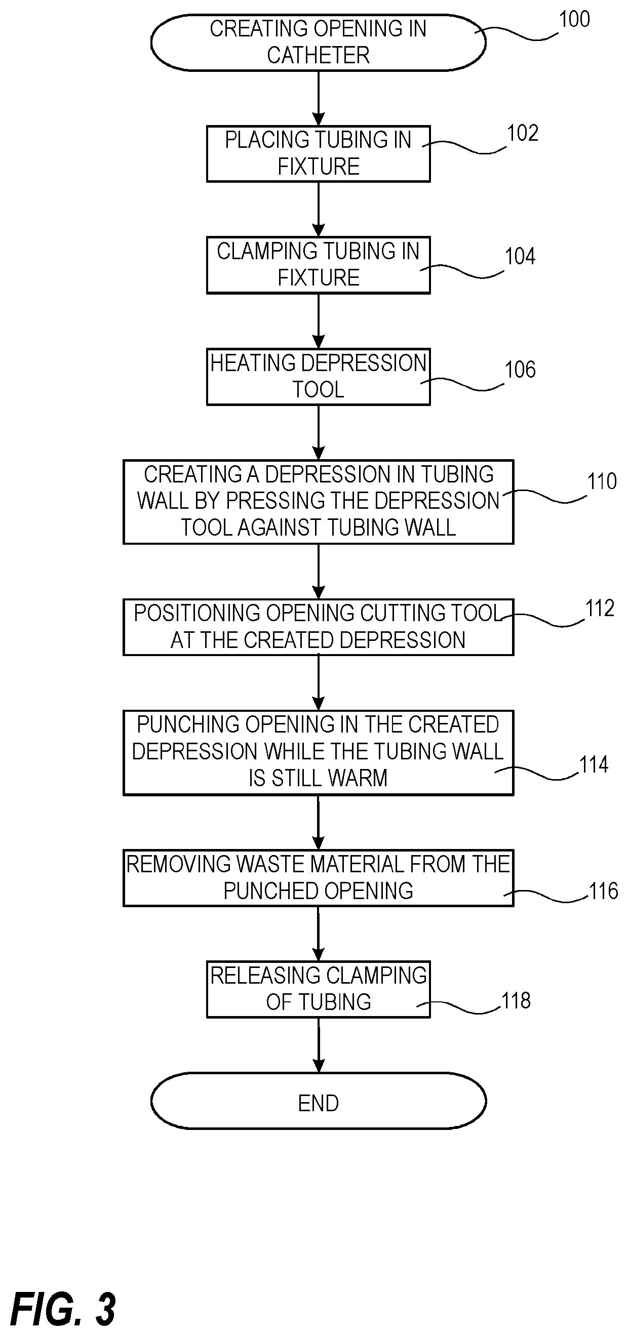
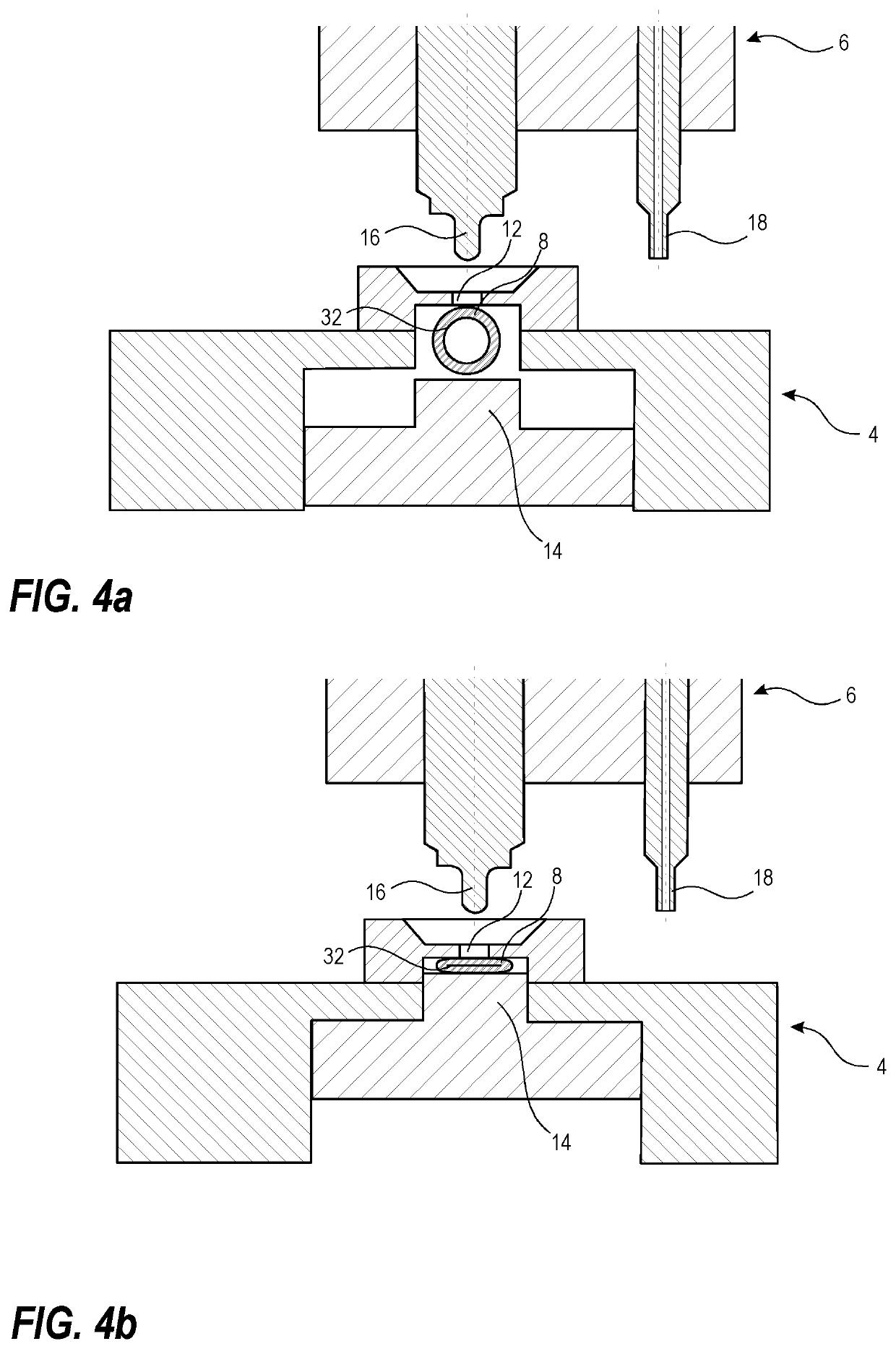
The patent describes a process for making openings in tubing for a catheter. The process involves placing the tubing in a fixture, applying force to fix the tubing in position, making a depression in the tubing wall, and punching an opening cutting tool through the depression area. This process makes it easier to make the opening and improves the quality of the catheter. It also reduces the risk of discomfort or harm for users or patients. Another advantage is that the process becomes more reliable and results in a decreased risk of discomfort or harm for users or patients. The depression area is typically 10%-30% of the area of the opening. The process may also involve punching the opening cutting tool through the tubing wall within the depression area. The heated depression tool is typically at a temperature below the melting point of the material in the tubing wall. The technical effects of this process include improved quality, easier manufacturing, and better user experience.

Problems solved by technology

This results from the fact that lesser precision, compared with the prior art, is required in the combination of operations for achieving an opening in the tubing that is not harming the body that the tubing is inserted into.
Moreover, this process also results in a decreased risk of discomfort or harm for users or patients that have to use or be treated using a catheter.

Method used


Image

  • Catheter and process for manufacturing a catheter
  • Catheter and process for manufacturing a catheter
  • Catheter and process for manufacturing a catheter

Examples


Embodiment Construction

[0027]Hereinafter, certain embodiments will be described more fully with reference to the accompanying drawings. It will be apparent to those skilled in the art that various modifications and variations can be made without departing from the inventive concept. Other embodiments will be apparent to those skilled in the art from consideration of the specification and practice disclosed herein. The embodiments herein are provided by way of example so that this disclosure will be thorough and complete, and will fully convey the scope of the inventive concept, and that the claims be construed as encompassing all equivalents of the present inventive concept which are apparent to those skilled in the art to which the inventive concept pertains. If nothing else is stated, different embodiments may be combined with each other.

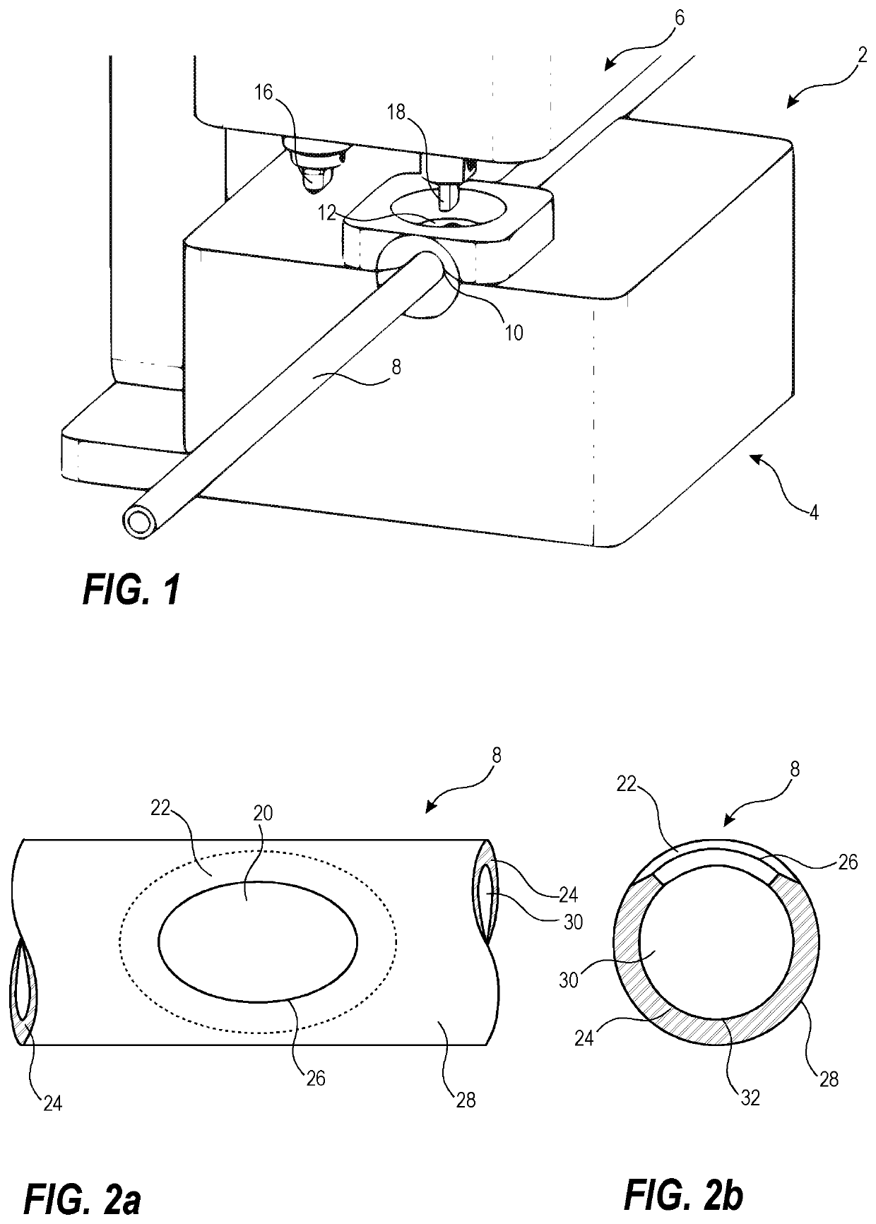
[0028]Now referring to FIG. 1, showing parts of a machine 2 arranged for making openings in tubing 8 during a process of manufacturing of a catheter according to some e...


PUM


Abstract

The present invention relates to a catheter and a process for manufacturing a radially extending opening in tubing for a catheter. The tubing having at least one lumen being enclosed by at least one tubing wall and the process comprises placing tubing in a fixture, applying force to the tubing and thereby fixing the tubing in the fixture in a position for making an opening, pressing a heated depression tool against the surface of the tubing creating a depression area in the at least one tubing wall, and punching an opening cutting tool through the at least one tubing wall within the depression area creating an opening in the depression area of the at least one tubing wall, the opening extending from the exterior of the tubing to the lumen of the tubing.

Description

TECHNICAL FIELD[0001]The present invention relates to processes for manufacturing a catheter and more specifically for manufacturing radially extending openings in tubing for a catheter. Further, the present invention relates to a catheter manufactured according to the process.BACKGROUND[0002]Catheters for insertion into human or animal bodies may include openings arranged to make the exterior to the catheter communicate with the lumen of the catheter, for example, for drainage, medication, exploration, dilation, and the like. Such catheters are often inserted into and / or through passages of the body, e.g. the urinary tract, the stomach, a lung, a blood vessel, the rectum, the urethra and ureter, and in such procedures it is important that the catheter does not have any sharp edges or sharp protrusions resulting in discomfort for the user or patient or, even worse, risking inflicting damage to the body. This problem has previously been identified and various solutions have been pres...

Claims


Application Information

Patent Timeline
Patent Type & Authority Applications(United States)
IPC IPC(8): A61M25/00B26F1/00
CPCA61M25/0015B26F1/0015B26D7/10B26D2007/0093B26F1/24
Inventor FORSRYD, GUSTAV JOAKIMPAULSSON, LARS RUNE BERTIL
Owner AUTOMATIONSPARTNER I HELSINGBORG AB
Learn More