Method, Apparatus and Software for monitoring and improving the efficiency of a heat exchange system

Pending Publication Date: 2022-08-11
KHOO CASS
View PDF0 Cites 0 Cited by
  • Summary
  • Abstract
  • Description
  • Claims
  • Application Information

AI Technical Summary

Benefits of technology

The invention provides a method for monitoring and improving the efficiency of a heat exchange system by using a cloud-based software program that analyzes data from a control box and adjusts the system accordingly. The control box receives input data from various components of the system and adjusts the expansion valve accordingly. The input data includes temperatures, humidity, and power. The software program generates optimal parameters for achieving maximum efficiency based on the input data and stores them in the control box and cloud system. The control box communicates with the expansion valve and other components of the system to achieve the optimal parameters. The invention also includes an efficiency-enhancing device that includes a refrigerant delivery tube and a means to create turbulent flow of the exiting refrigerant. The technical effects of the invention include improved efficiency of heat exchange systems and reduced energy consumption.

Problems solved by technology

However, at varying environmental conditions, for e.g. on a hot humid day or on a cooler day, the superheat value deviates excessively from the set value while trying to reach the set value.
On a very hot and humid day, the manufacturer's preset superheat value is high, which means there is insufficient refrigerant in the evaporator for the heat load present.
This could mean not enough refrigerant is entering the evaporator coil causing excessive load on the evaporator coil.
As a result, the compressor becomes hot due to too little refrigerant thereby reducing the efficiency and life span of the AC system.
Likewise on a cooler day, when the outside temperature is low, too much refrigerant enters the evaporator causing damage to the compressor.
If the temperature falls outside this range i.e. too high or too low an ambient temperature, the system will be inefficient, ineffective and may damage or shorten the life of the compressor.

Method used


Image

  • Method, Apparatus and Software for monitoring and improving the efficiency of a heat exchange system
  • Method, Apparatus and Software for monitoring and improving the efficiency of a heat exchange system
  • Method, Apparatus and Software for monitoring and improving the efficiency of a heat exchange system

Examples


Embodiment Construction

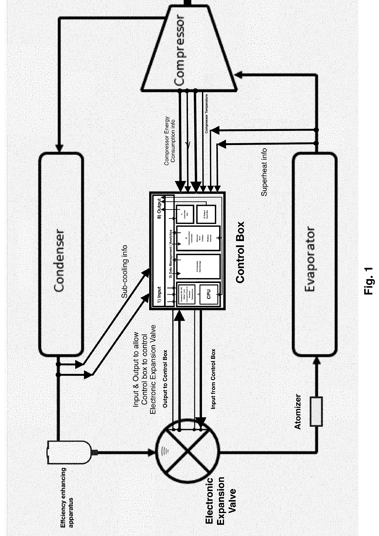
[0018]This disclosure is directed to techniques to enhance the efficiency of a heat exchange system using machine learning and Artificial Intelligence techniques. FIG. 1 shows the heat exchange system with the various components including the compressor, condenser, the expansion valve and evaporator. Also shown is the Control Box connected to the expansion valve.

[0019]In addition to these basic components, the system comprises an efficiency enhancing apparatus positioned between the condenser and the evaporator, which receives a portion of the liquid refrigerant flowing from the condenser. The heat exchange system further includes an atomizer or atomizing device incorporated into the refrigerant path downstream of the expansion valve and before the evaporator coil. The atomizer preferably includes an incremental expansion device disk which develops a low pressure area on the back side. A heat exchanger on the outside of the atomizer may be used to remove any heat the expansion devic...


PUM


Abstract

A method of improving the efficiency of the heat exchange system using variable superheat and sub cooling values for a wide range of ambient conditions is provided. The heat exchange system comprises an efficiency enhancing apparatus positioned between the condenser and evaporator. Data analytics software module and artificial intelligence techniques are used to obtain optimum system parameters for achieving maximum efficiency.

Description

CROSS-REFERENCE TO RELATED APPLICATION[0001]This patent application claims the priority benefit under 35 U.S.C. § 119(e) of U.S. Provisional Applications No. 63 / 142,454 filed on Jan. 27, 2021, the contents of which are herein incorporated by reference.FIELD OF THE INVENTION[0002]The present invention relates generally to heat exchange systems and particularly to refrigeration and air conditioning devices. More specifically, this invention relates to cloud based and computer-implemented methods of enhancing the efficiency of a heat exchange system.BACKGROUND OF THE INVENTION[0003]Various devices relying on standard refrigerant recycling technologies have been available for many years, such as refrigeration and heat pump devices, having both cooling and heating capabilities. Within the limits of each associated design specification, heat pump devices enable a user to cool or heat a selected environment or with a refrigeration unit to cool a desired location. For these heating and cool...

Claims


Application Information

Patent Timeline
IPC IPC(8): F25B49/02F25B39/00F25B40/00F25B41/45
CPCF25B49/02F25B39/00F25B40/00F25B41/45F25B2700/2106F25B2500/09F25B2600/2513F25B2700/02F25B2600/07
Inventor KHOO, CASS
Owner KHOO CASS
Why Eureka
Try Eureka