Heat exchanging system

Inactive Publication Date: 2013-11-21
DELTA ELECTRONICS INC
View PDF9 Cites 1 Cited by
  • Summary
  • Abstract
  • Description
  • Claims
  • Application Information

AI Technical Summary

Benefits of technology

The invention is a heat exchanging system that uses a magnetic refrigerator to cool or warm a building by exchanging heat with the surrounding ground. This improves the efficiency of heat exchanging and reduces the use of conventional compressor refrigerators, which are quieter, produce less vibrations, and consume less electrical energy. The technical effect of the invention is improved energy efficiency and more comfortable building temperatures.

Problems solved by technology

In effect, gases such as the CFCs (chlorofluorocarbons) currently used as the cooling fluid are serious pollutants and their use entails great risks for atmospheric pollution and destruction of the ozone layer.
Consequently, those gases do not satisfy present-day requirements, nor the environmental standards of many countries.
Furthermore, such conventional equipment, which operates under pressure, has to be installed and maintained by trained and certified personnel who must follow constraining procedures with lengthy, numerous and highly demanding implementation requirements.
Finally, such equipment is noisy, produces vibrations, is bulky and complex, and consumes a lot of electrical energy.
So conventional devices are not satisfactory.

Method used


Image

  • Heat exchanging system
  • Heat exchanging system
  • Heat exchanging system

Examples


first embodiment

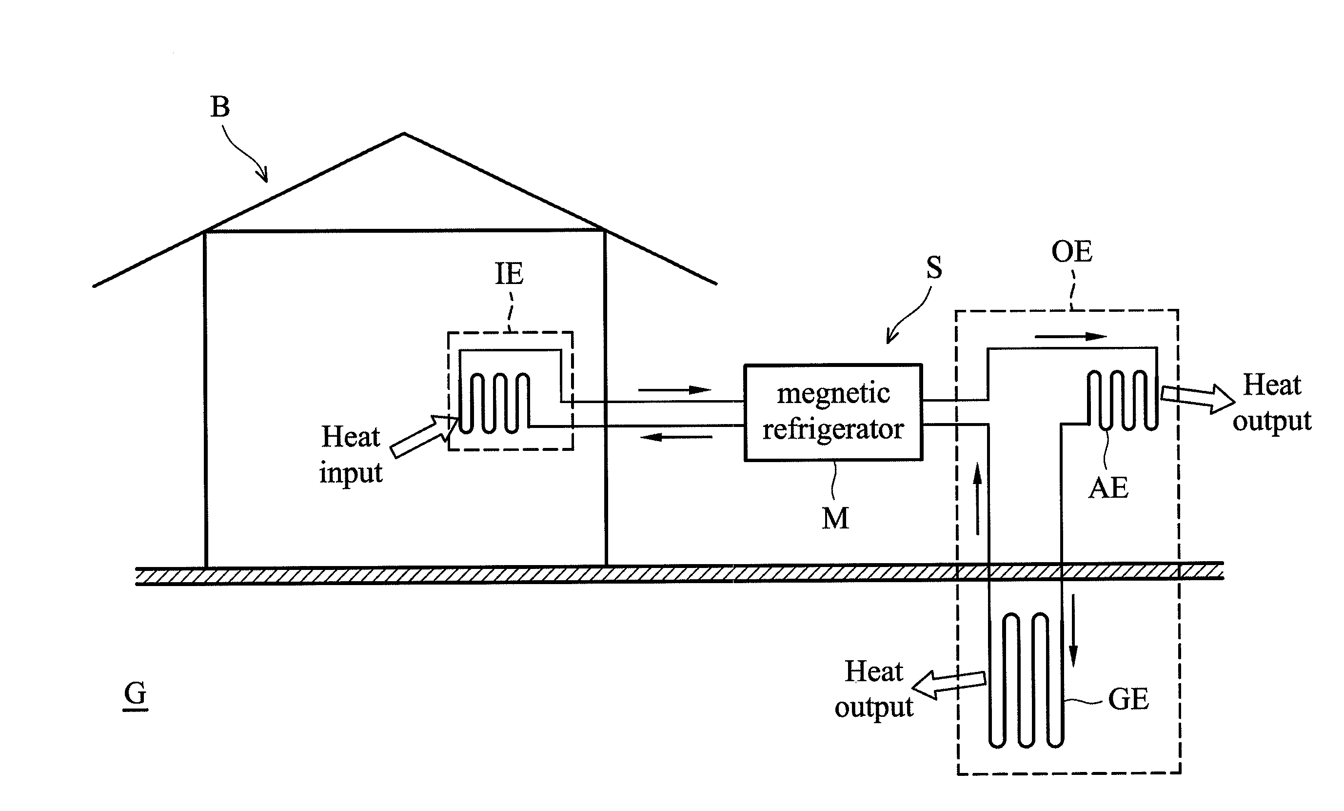
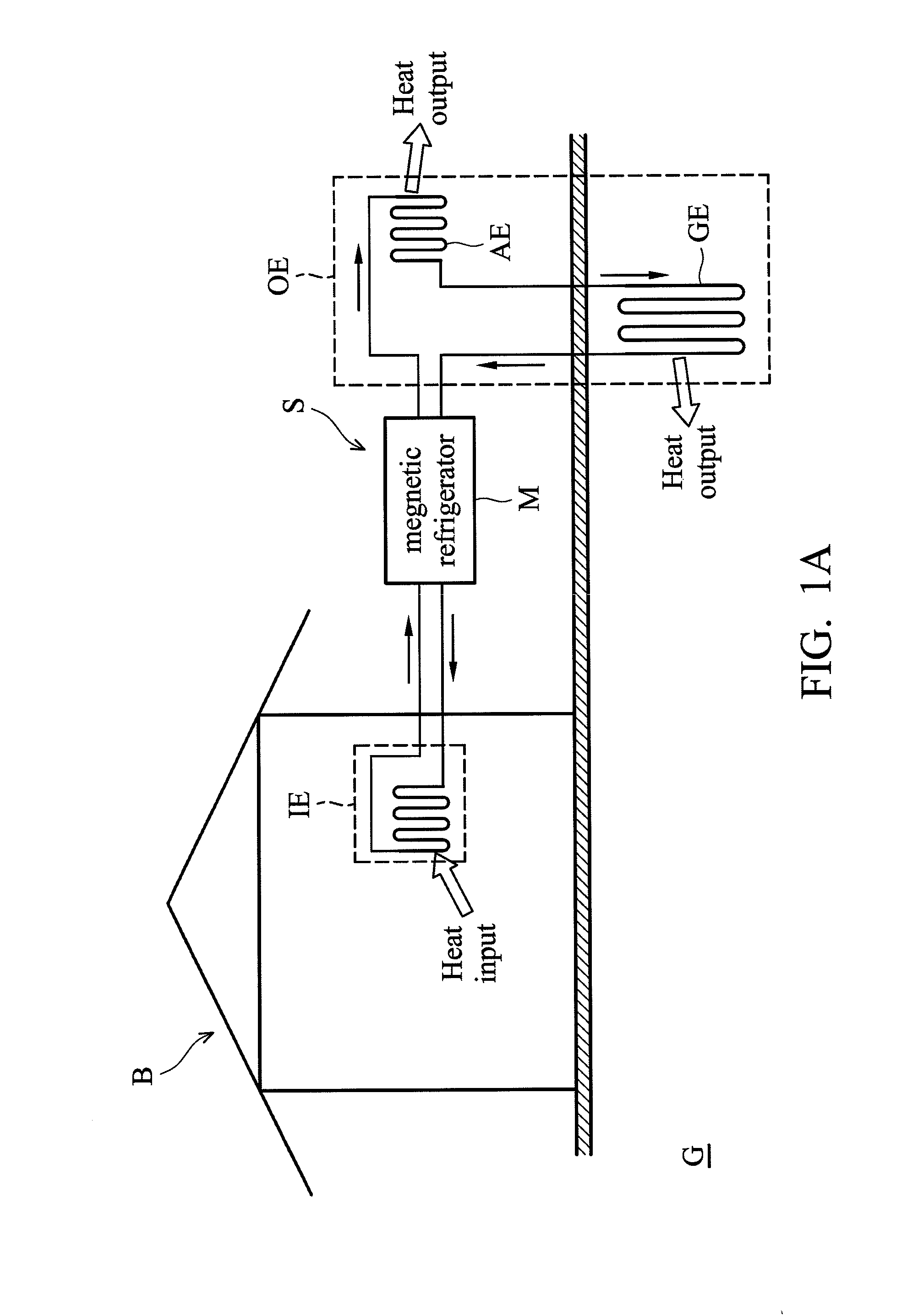
[0018]FIG. 1A shows a heat exchanging system S of the invention for conditioning indoor temperature of a building B (building body). The heat exchanging system S comprises a magnetic refrigerator M, an indoor heat exchanger IE and an outdoor heat exchanger OE. The indoor heat exchanger IE is disposed inside of the building B (building body) and is thermally connected to the magnetic refrigerator M. The outdoor heat exchanger OE is disposed outside of the building B (building body) and is thermally connected to the magnetic refrigerator M. The outdoor heat exchanger OE comprises a geothermal heat exchanging unit GE, wherein the geothermal heat exchanging unit GE is embedded under a ground G of the building B.

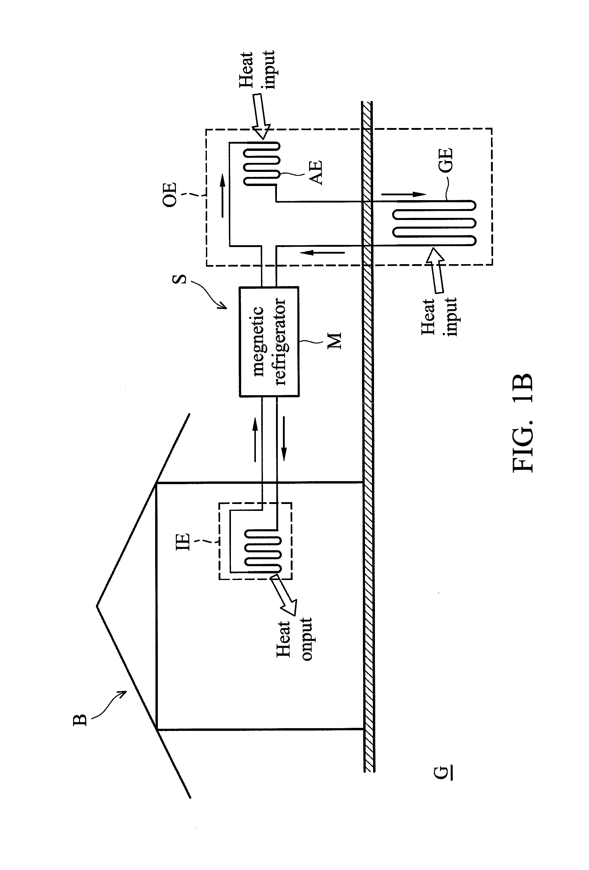
[0019]As shown in FIG. 1A, in a cooling state, heat inside of the building B is moved by the magnetic refrigerator M from the indoor heat exchanger IE to the outdoor heat exchanger OE to be dissipated to the ground. With reference to FIG. 1B, in a heating state, heat from the gro...

second embodiment

[0022]FIG. 3A shows a heat exchanging system S″ of the invention, wherein a geothermal heat exchanging unit GE″ of an outdoor heat exchanger OE″ comprises an outer path GE1, an inner path GE2 and an insulation layer GE3, wherein the insulation layer GE3 separates the outer path GE1 and the inner path GE2. The outdoor heat exchanging fluid travels from the magnetic refrigerator M, along the inner path GE2, and then travels back to the magnetic refrigerator M via the outer path GE1 to exchange heat with the ground G. With reference to FIG. 3B, FIG. 3B shows a cross-section along direction 3B-3B′ of FIG. 3A.

[0023]Utilizing the heat exchanging system of the embodiment of the invention, in the summer, a temperature of a building is higher than a temperature of the ground, and the magnetic refrigerator moves the heat from the building to the ground to cool the building. In the winter, a temperature of a building is lower than a temperature of the ground, and the magnetic refrigerator move...


PUM


Abstract

A heat exchanging system is provided for conditioning indoor temperature of a building. The heat exchanging system includes a magnetic refrigerator, an indoor heat exchanger and an outdoor heat exchanger. The indoor heat exchanger is thermally connected to the magnetic refrigerator. The outdoor heat exchanger is thermally connected to the magnetic refrigerator. The outdoor heat exchanger includes a geothermal heat exchanging unit, wherein the geothermal heat exchanging unit is embedded under the ground of a building.

Description

BACKGROUND OF THE INVENTION[0001]1. Field of the Invention[0002]The present invention relates to a heat exchanging system, and in particular relates to a heat exchanging system with a magnetic refrigerator.[0003]2. Description of the Related Art[0004]Conventional refrigeration devices usually comprise a compressor for compressing a cooling fluid in order to raise its temperature and expansion means to decompress a cooling fluid in order to cool it adiabatically. These conventional devices have a number of disadvantages. In effect, gases such as the CFCs (chlorofluorocarbons) currently used as the cooling fluid are serious pollutants and their use entails great risks for atmospheric pollution and destruction of the ozone layer. Consequently, those gases do not satisfy present-day requirements, nor the environmental standards of many countries. Furthermore, such conventional equipment, which operates under pressure, has to be installed and maintained by trained and certified personnel...

Claims


Application Information

Patent Timeline
IPC IPC(8): F25B21/00
CPCY02B10/40F24D15/00F24D2200/11F24F5/0046Y02B10/20Y02A30/272F24T10/17Y02E10/10
Inventor IRINO, YASUMIHSIEH, SHENG-FANWANG, MIN-CHIAWU, TIAO-YUANCHANG, CHIEH-SHIH
Owner DELTA ELECTRONICS INC
Why Eureka
Try Eureka