
Object-based change detection using a neural network

a neural network and object-based technology, applied in scene recognition, instruments, computing, etc., can solve the problems of unneeded reactions, high number of false positive change detections, and cloud may be considered nois

Pending Publication Date: 2022-08-04
NEO NETHERLANDS GEOMATICS & EARTH OBSERVATION BV
View PDF0 Cites 11 Cited by
  • Summary
  • Abstract
  • Description
  • Claims
  • Application Information

AI Technical Summary

Benefits of technology

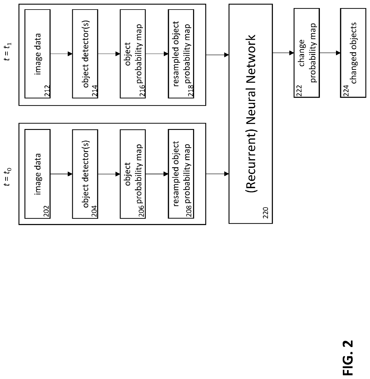
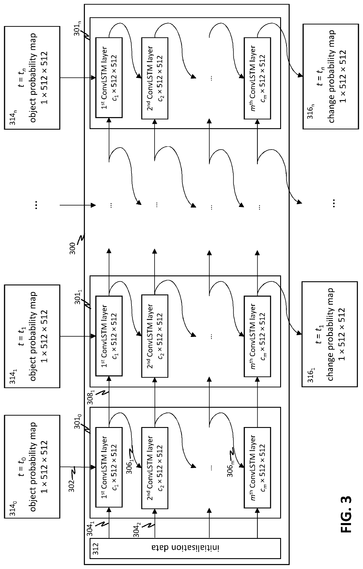
This patent describes a method for detecting changes in objects using a combination of object-based and pixel-based techniques. The method involves using dedicated object detectors, such as neural networks, to provide high quality input and reduce sensitivity to noise and misclassification. The object probability maps generated by the detectors are compared using a neural network to determine the change in the object(s) of interest. This approach allows for comparison of dissimilar remote sensing data and makes it easier to detect changes in objects of interest. The network can also be trained to detect specific changes and provide additional information to improve accuracy. The use of modularised object detectors and additional data can further improve the interpretation of the results.

Problems solved by technology

One of the difficulties in automated change detection is avoiding a high rate of false positives, which may lead to unneeded reactions.
Similarly, weather applications may be interested in clouds, while clouds may be considered noise for applications interested in land use.
However, the method of Song et al. also has various drawbacks.
For example, the method does not discriminate well between relevant and irrelevant changes, and may therefore yield a high number of false positive change detections.
Additionally, the method is sensitive to misclassification of pixels, and is not suitable for comparing images from different image sources (e.g. sensors operating at different wavelengths).
Although reference is made to multitemporal images, the examples and embodiments in the text are limited to comparisons of only two time instances.

Method used


Image

  • Object-based change detection using a neural network
  • Object-based change detection using a neural network
  • Object-based change detection using a neural network

Examples


Embodiment Construction

[0056]In this disclosure embodiments are described of methods and systems to determine a change in an object or class of objects based on image data, preferably remote sensing data. The methods and systems will be described hereunder in more detail. An objective of the embodiments described in this disclosure is to determine changes in pre-determined objects or classes of objects in a geographical region.

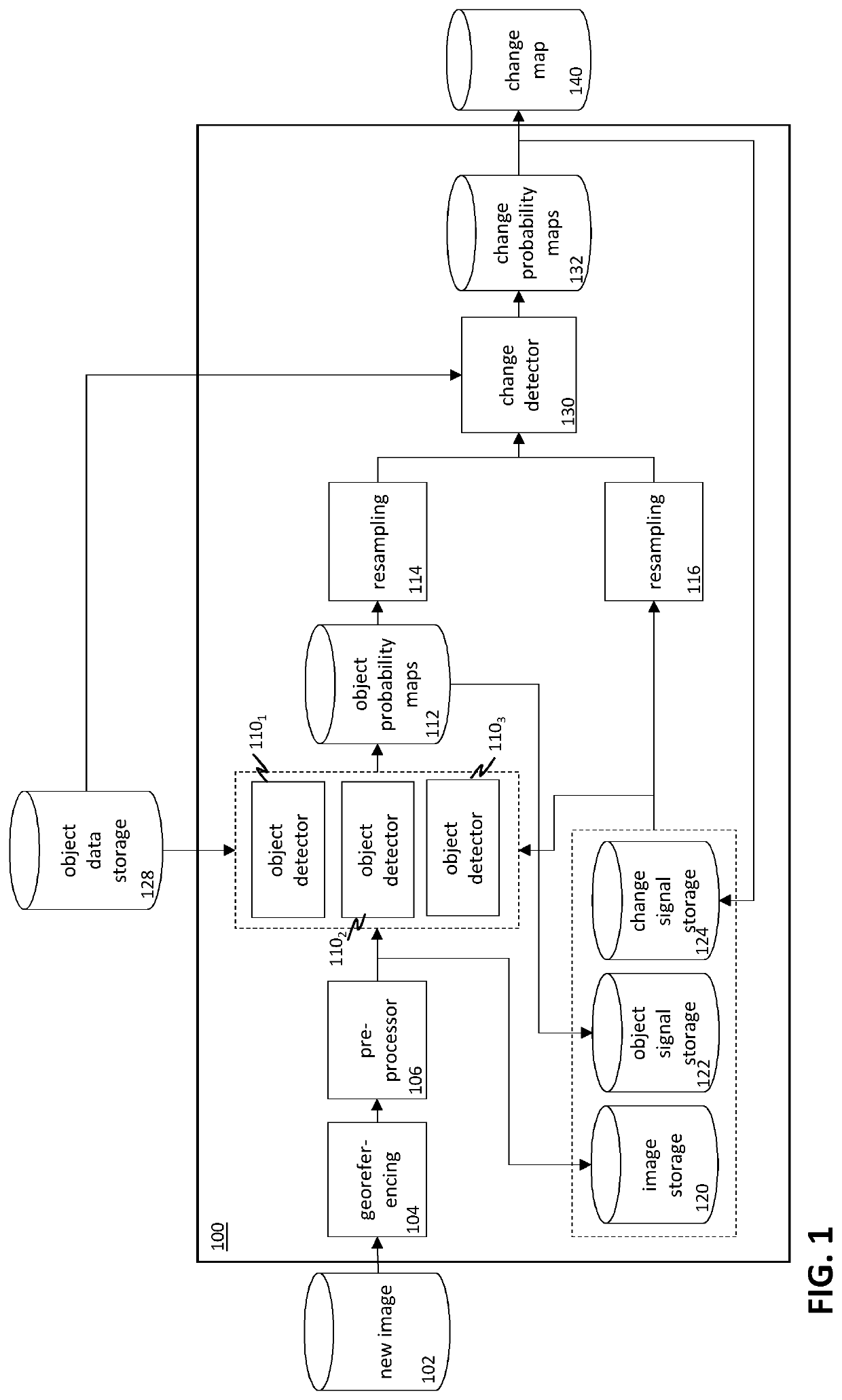
[0057]FIG. 1 schematically depicts a system for reliable object-based change detection in remote sensing data according to an embodiment of the invention. When a new image 102, typically an aerial image or satellite image, is received by the image processing and storage system 100, the image may be georeferenced 104, i.e. the internal coordinates of the image may be related to a ground system of geographic coordinates. Georeferencing may be performed based on image metadata, information obtained from external providers such as Web Feature Service, and / or matching to images with know...


PUM


Abstract

A method is described for determining a change in an object or class of objects in image data, wherein the method comprises: receiving a first image data set of a geographical region associated with a first time instance and receiving a second image data set of the geographical region associated with a second time instance; determining a first object probability map on the basis of the first image data set and a second object probability map on the basis of the second image data set, a pixel in the first and second object probability maps having a pixel value, the pixel value representing a probability that the pixel is associated with the object or class of objects; providing the first object probability map and the second object probability map to an input of a neural network, preferably a recurrent neural network, the neural network being trained to determine a probability of a change in the object or class of objects, based on the pixel values in the first object probability map and in the second object probability map; receiving an output probability map from an output of the neural network, a pixel in the output probability map having a pixel value, the pixel value representing a probability of a change in the object or class of objects; and, determining a change in the object or class of objects in the geographical region, based on the output probability map.

Description

FIELD OF THE INVENTION[0001]The invention relates to determining a change in an object or class of objects in image data, preferably remote sensing data; and, in particular, though not exclusively, to methods and systems for determining a change in an object or class of objects in image data, preferably remote sensing data and a computer program product enabling a computer system to perform such methods.BACKGROUND OF THE INVENTION[0002]Remote sensing data, such as satellite data and aerial image data, may be used for a wide variety of purposes, such as creating and updating maps, monitoring land cover and land use, water management, et cetera. Any monitored entity, e.g. a building, field, or road, may be considered an ‘object’. For many purposes, detecting changes in such objects, e.g. new buildings, cut down trees, or additional lanes on a road, is especially relevant, as they may indicate a need for action, such as updating a map, or checking building permits or logging concession...

Claims


Application Information

Patent Timeline
Patent Type & Authority Applications(United States)
IPC IPC(8): G06V20/13G06V10/82G06V10/24G06V10/764
CPCG06V20/13G06V10/764G06V10/242G06V10/82G06F18/2413
Inventor VALK, ARIE CORNELISBECK, ROBERT
Owner NEO NETHERLANDS GEOMATICS & EARTH OBSERVATION BV
Learn More