Antenna device
a technology of antenna and antenna body, applied in the direction of the structure of the antenna, can solve the problems of inability to meet the needs of the user, lack of waterproof function, and opaque structure of the conventional antenna body, and achieve the effect of effectively improving the problem of the associated structur
- Summary
- Abstract
- Description
- Claims
- Application Information
AI Technical Summary
Benefits of technology
Problems solved by technology
Method used
Image
Examples
first embodiment
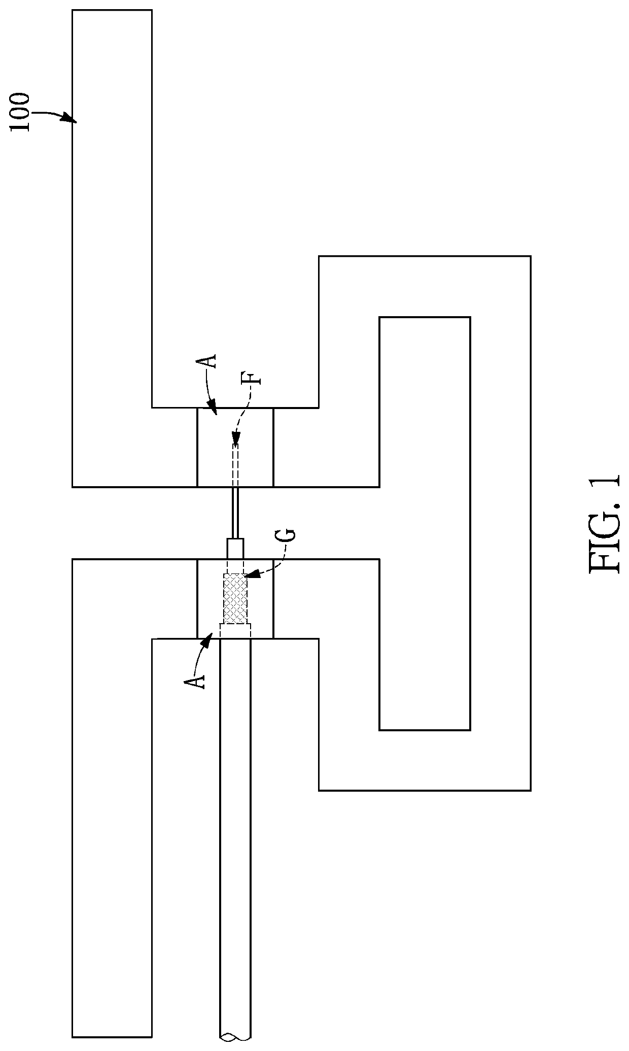
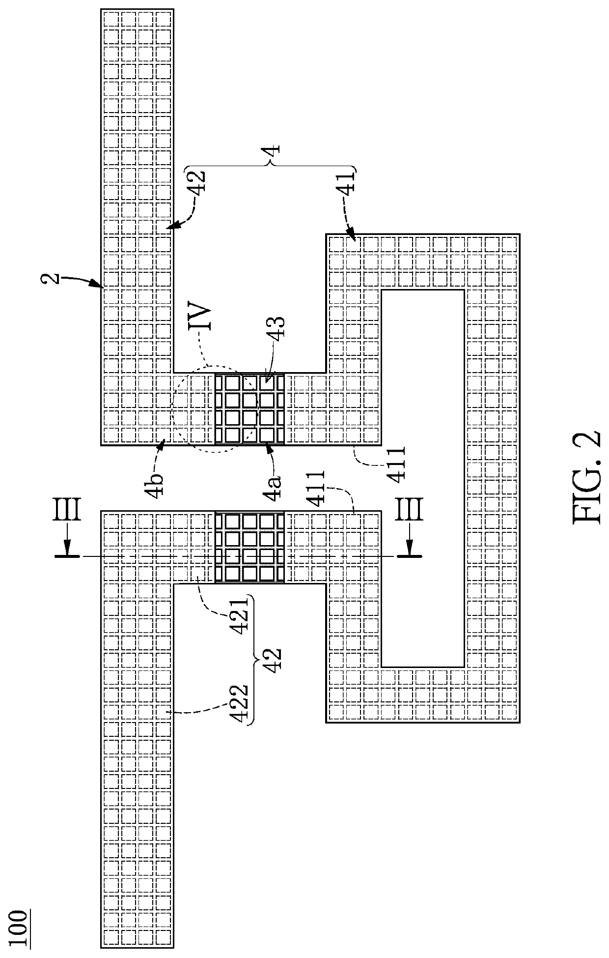
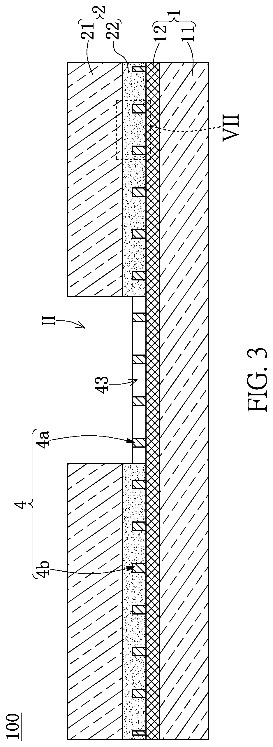
[0022]Referring to FIG. 1 to FIG. 7, a first embodiment of the present disclosure provides an antenna device 100 having a waterproof function (or a water vapor resistance function). As shown from FIG. 1 to FIG. 3, the antenna device 100 in the present embodiment includes an antenna layer 4, a first transparent layer 1, and a second transparent layer 2. The first transparent layer 1 and the second transparent layer 2 are respectively connected to two opposite sides of the antenna layer 4.
[0023]As shown from FIG. 2 to FIG. 4, the antenna layer 4 is a metal mesh structure having a plurality of thru-holes 43, and an open ratio of the thru-holes 43 of the antenna layer 4 in the present embodiment is within a range from 60% to 99%. Moreover, the open ratio in the present embodiment indicates that the thru-holes 43 occupy 60% to 99% of an area surrounded by an outer contour of the antenna layer 4.
[0024]Accordingly, in the antenna device 100 of the present embodiment, the thru-holes 43 are ...
second embodiment
[0038]Referring to FIG. 8, a second embodiment of the present disclosure is similar to the first embodiment of the present disclosure. For the sake of brevity, descriptions of the same components in the first and second embodiments of the present disclosure will be omitted herein, and the following description only discloses different features between the first and second embodiments.
[0039]In the present embodiment, the antenna device 100 further includes a bonding layer 5 and a release film 6. The bonding layer 5 is formed on a surface of the first transparent layer 1 (e.g., a bottom surface of the first substrate 11 shown in FIG. 8) away from the antenna layer 4, and the release film 6 is detachably connected to the bonding layer 5.
[0040]Accordingly, the antenna device 100 in the present embodiment is provided by forming the bonding layer 5 onto the first transparent layer 1, so that the antenna device 100 can be easily fixed to a predetermined position according to user requireme...
third embodiment
[0041]Referring to FIG. 9, a third embodiment of the present disclosure is similar to the first embodiment of the present disclosure. For the sake of brevity, descriptions of the same components in the first and third embodiments of the present disclosure will be omitted herein, and the following description only discloses different features between the first and third embodiments.
[0042]In the present embodiment, a thickness of the first substrate 11 is limited to being within a range from 5 μm to 300 μm. The antenna device 100 further includes a third transparent layer 3 connected to a surface of the first substrate 11 (e.g., a bottom surface of the first substrate 11 shown in FIG. 9) away from the antenna layer 4, thereby increasing a structural strength of the antenna device 100.
[0043]The third transparent layer 3 includes a third substrate 31 and an adhering layer 32, and the third substrate 31 is connected to the first substrate 11 through the adhering layer 32. Moreover, a thi...
PUM
 Abstract
Description
Claims
Application Information
 - R&D
- Intellectual Property
- Life Sciences
- Materials
- Tech Scout
- Unparalleled Data Quality
- Higher Quality Content
- 60% Fewer Hallucinations
Browse by: Latest US Patents, China's latest patents, Technical Efficacy Thesaurus, Application Domain, Technology Topic, Popular Technical Reports.
© 2025 PatSnap. All rights reserved.Legal|Privacy policy|Modern Slavery Act Transparency Statement|Sitemap|About US| Contact US: help@patsnap.com


