
Method implemented by computer means of a communicating entity in a packet-switched network, and computer program and computer-readable non-transient recording medium thereof, and communicating entity of a packet-switched network

a communication entity and packet-switched technology, applied in the field of data frame transmission, can solve the problems that the obtained network configuration cannot be changed, and the standard 802.1qbv imposes some limitations, and achieves the effect of improving the situation

Pending Publication Date: 2022-06-30
MITSUBISHI ELECTRIC CORP
View PDF6 Cites 0 Cited by
  • Summary
  • Abstract
  • Description
  • Claims
  • Application Information

AI Technical Summary

Benefits of technology

This patent allows for keeping track of transmission scheduling and allows for the reserving of fields in a signaling frame for any other data type.

Problems solved by technology

In addition, the obtained network configuration can only be changed by performing a new off-line computation and redistributing the new configuration to all the involved nodes.
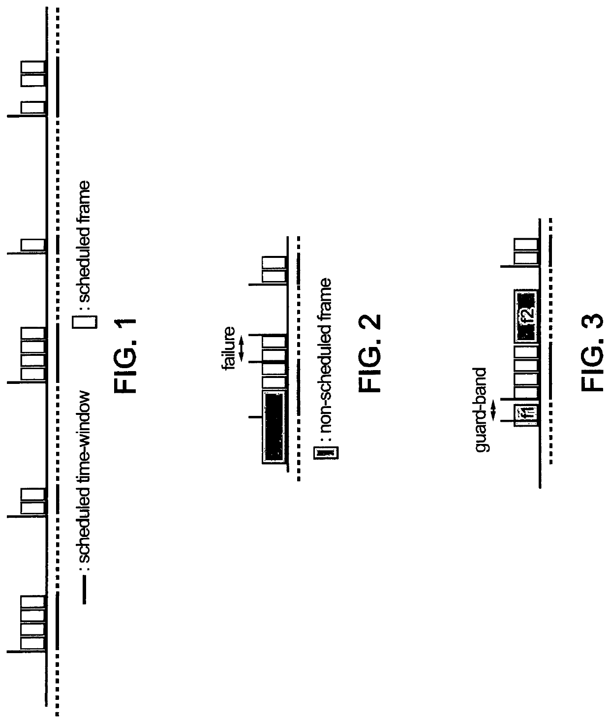
Implementing scheduled stream through the standard 802.1Qbv also imposes some limitations due to the nature of the calendar table used to define the different time windows reserved to scheduled streams.

Method used


Image

  • Method implemented by computer means of a communicating entity in a packet-switched network, and computer program and computer-readable non-transient recording medium thereof, and communicating entity of a packet-switched network
  • Method implemented by computer means of a communicating entity in a packet-switched network, and computer program and computer-readable non-transient recording medium thereof, and communicating entity of a packet-switched network
  • Method implemented by computer means of a communicating entity in a packet-switched network, and computer program and computer-readable non-transient recording medium thereof, and communicating entity of a packet-switched network

Examples


Embodiment Construction

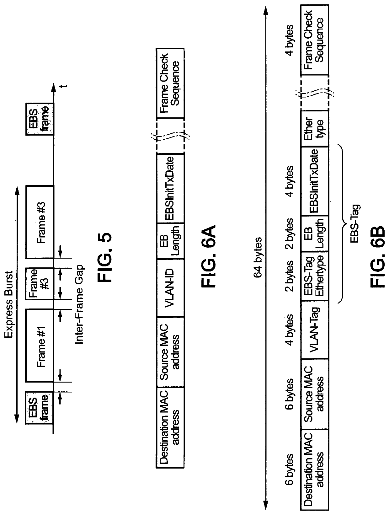
[0073]The invention targets so-called Real Time Ethernet networks such as those used in industrial automation, in-vehicle control or train control applications. It proposes to organise “Express Bursts” (in the sense defined by the Ethernet TSN standards on pre-emption) of frames of low latency communications as a train of frames delineated by specific short frames used each to signal the beginning of each Express Burst. This explicit in-band Express Burst delineation is used to trigger pre-emption operations on “Normal frames” (as defined in TSN standards on pre-emption) possibly interfering with the Express Bursts and to manage possibly the multiplexing of simultaneous incident Express Bursts.

[0074]The transmission of the express burst can be synchronised with a cycle common to the whole network. In that case, the express bursts can be sent by the so-called “Talkers” (emitters) at a given common time during the cycle and are multiplexed in the ports where they collide using the exp...


PUM


Abstract

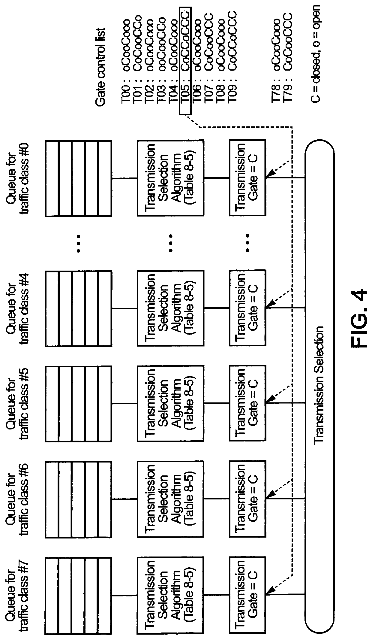
The invention relates to transmission of communication signal frames by a communicating entity in a packet-switched network, the communicating entity comprising an egress port for transmitting communication signal frames. The frames comprise a first type of frames, intended to be transmitted in a plurality of bursts for which a traffic shaping is defined as an express traffic, and a second type of frames, for which no traffic shaping is defined, as a sporadic traffic. The communicating entity is configured for storing a plurality of first queues of frames of the first type, associated respectively to the aforesaid plurality of bursts, and at least one second queue for frames of the second type. The bursts are stored in respective first queues with a signaling frame preceding each burst, and this signaling frame comprises a timestamp of generation of said burst. Then, for selecting a first burst to transmit among the bursts stored in said first queues, the communicating entity is configured for: —Reading the timestamp of each signaling frame located at a head of each first queues, —Determining among all the signaling frames the one having the most ancient timestamp, and —Select the burst having the thus determined signaling frame as the first burst to transmit.

Description

TECHNICAL FIELD[0001]The present invention relates to telecommunications and more particularly to data frames transmission.BACKGROUND ART[0002]Packet-switched networks are increasingly used for industrial control application thanks to the introduction of Layer-2 features allowing control data transport with tightly bounded latency and transfer delay variation.[0003]For instance, low-latency sampling data, (closed loop) control and image streaming (e.g. for real-time image processing) have very stringent latency requirements. Image streaming and associated processing as a part of a control loop has greater requirements than best effort transport could provide in a converged network.[0004]In parallel, best effort stream is not time-critical, but provides a constant source of interference for the time-critical streams.[0005]Solutions have been progressively developed, in particular for the adaptation of switched Ethernet to the requirements of industrial field busses: EtherCAT, Etherne...

Claims


Application Information

Patent Timeline
Patent Type & Authority Applications(United States)
IPC IPC(8): H04L47/22H04L47/6275H04L47/31
CPCH04L47/225H04L47/6275H04L47/31H04L47/28H04L47/24H04L47/245H04L47/6215
Inventor MANGIN, CHRISTOPHE
Owner MITSUBISHI ELECTRIC CORP
Learn More