Control device, suspension system, and saddle-type vehicle
- Summary
- Abstract
- Description
- Claims
- Application Information
AI Technical Summary
Benefits of technology
Problems solved by technology
Method used
Image
Examples
first embodiment
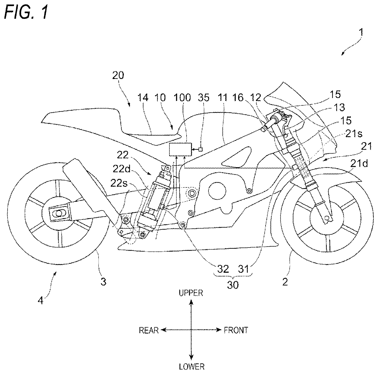
[0028]FIG. 1 is a diagram illustrating an example of a schematic configuration of the motorcycle 1 according to the first embodiment.
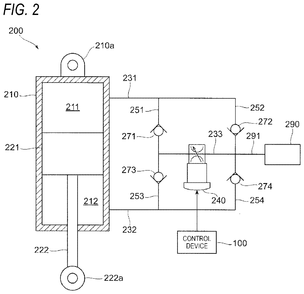
[0029]FIG. 2 is a diagram illustrating an example of a schematic configuration of a damping device 200.
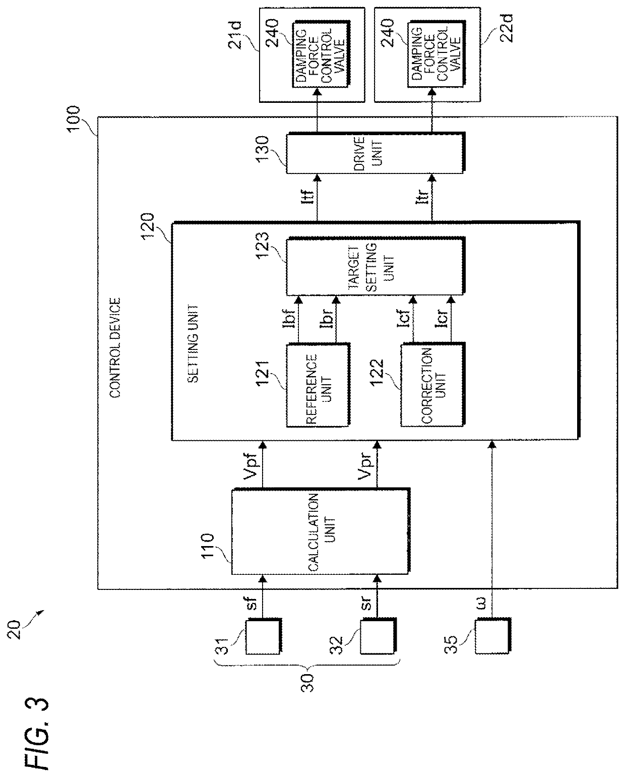
[0030]FIG. 3 is a diagram illustrating an example of a schematic configuration of a control device 100.
[0031]The motorcycle 1 as an example of the saddle-type vehicle includes a front wheel 2, a rear wheel 3, and a vehicle body 10. The vehicle body 10 includes a vehicle body frame 11, a handle 12, a brake lever 13, and a seat 14.
[0032]The motorcycle 1 includes a suspension 21 on a front wheel side, two brackets 15 holding two suspensions 21, and a shaft 16 disposed between the two brackets 15. The suspension 21 includes a suspension spring 21s which absorbs an impact applied to the front wheel 2 from a road surface or the like, and a damping device 21d which damps vibration of the suspension spring 21s.
[0033]The motorcycle 1 further includes a suspen...
second embodiment
[0098]FIG. 8 is a schematic diagram of a control map illustrating an example of a relationship between the reference correction current Icbf and the velocity Vpf used when a reference correction unit according to the second embodiment calculates the reference correction current Icbf.
[0099]A control device of the motorcycle according to the second embodiment differs from the control device 100 according to the first embodiment in the control map illustrating the relationship between the reference correction current Icb and the velocity Vp used when the reference correction unit according to the second embodiment, which corresponds to the reference correction unit 141, calculates the reference correction current Icb. Hereinafter, differences between the control map illustrating an example of the relationship between the reference correction current Icbf and the velocity Vpf illustrated in FIG. 8 used in the second embodiment and the control map according to the first embodiment will b...
third embodiment
[0108]FIG. 9 is a schematic diagram of a control map illustrating an example of a relationship between the reference correction current Icbf and the velocity Vpf used when a reference correction unit according to the third embodiment calculates the reference correction current Icbf.
[0109]A control device of the motorcycle according to the third embodiment differs from the control device 100 according to the first embodiment in the control map illustrating an example of the relationship between the reference correction current Icb and the velocity Vp used when the reference correction unit according to the third embodiment, which corresponds to the reference correction unit 141, calculates the reference correction current Icb. Hereinafter, differences between the control map illustrating an example of the relationship between the reference correction current Icbf and the velocity Vpf illustrated in FIG. 9 used in the third embodiment and the control map according to the first embodim...
PUM
 Abstract
Description
Claims
Application Information
 - R&D
- Intellectual Property
- Life Sciences
- Materials
- Tech Scout
- Unparalleled Data Quality
- Higher Quality Content
- 60% Fewer Hallucinations
Browse by: Latest US Patents, China's latest patents, Technical Efficacy Thesaurus, Application Domain, Technology Topic, Popular Technical Reports.
© 2025 PatSnap. All rights reserved.Legal|Privacy policy|Modern Slavery Act Transparency Statement|Sitemap|About US| Contact US: help@patsnap.com


