Safety Device

a safety device and a technology for stairways, applied in the direction of stairway-like structures, building components, paving details, etc., can solve the problems of tabs projecting outwards, easy to be affected by vertical and horizontal movement/play, and the option is not easily applicable, so as to achieve the effect of being more robust and convenient to us

Pending Publication Date: 2022-06-09
LEROUX ANDRE
View PDF0 Cites 0 Cited by
  • Summary
  • Abstract
  • Description
  • Claims
  • Application Information

AI Technical Summary

Benefits of technology

The invention is an attachment device for attachment to a pathway, which has a body with at least one point of flexure and an arm that can engage with the pathway or a structural member of the pathway to secure the device. The attachment device can be easily attached to a grating-type surface, providing a safer and more robust method of attaching a safety device on grating-type surfaces. It can be attached to pathways surfaces with load bars of varying depths, without interference with structural supports that ensure the structural integrity of the pathway. The attachment device creates a device attachment bias with the pathway or the structural member of the pathway to minimize movement of the device. The device can be placed along a surface, in a grating-type surface, in a way that creates a uniform non-slip pattern / surface. The device can securely rest between at least two structural members, or between three structural members, with a central member positioned in a recess or opening in the device. The device is versatile and can be manufactured and tailored to different environments.

Problems solved by technology

Where the path or thoroughfare is an open structure, then such options are not easily applicable.
Further, as is the case with Australian Patent 2012202911, these accessories are often snap-fit devices which snap onto single portions of grating, and are susceptible to vertical and horizontal movement / play.
However, the device of Korean Patent KR200459894Y1 comprises locking tabs which when the arms reach a certain depth below a load bar, the tabs project outwards and obstruct the upward movement of the fitting.
The existing prior art is limited in that it provides fittings that cannot accommodate cross bars.
Where part of the anti-slip feature deteriorates, often the entire feature will require replacement.
Further, placement of tiles or plates on top of grating is not desirable as it counteracts the numerous advantages of grating, for example, it causes water to pool, creating a safety hazard, and also removes the advantage of having light travel through the grating.
However application of an anti-slip coating to grating has been found to be time consuming, ineffective and expensive.
Also, where the coating is applied in an outdoor environment, the sheen of the coat may result in a high amount of reflection of light, and create a safety hazard.
A further disadvantage of relying on the application of an anti-slip coating is that it requires ongoing and regular maintenance / replenishment.

Method used


Image

  • Safety Device
  • Safety Device
  • Safety Device

Examples


Embodiment Construction

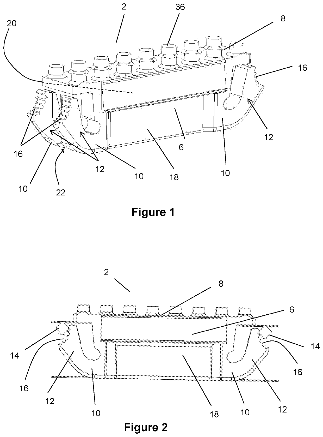
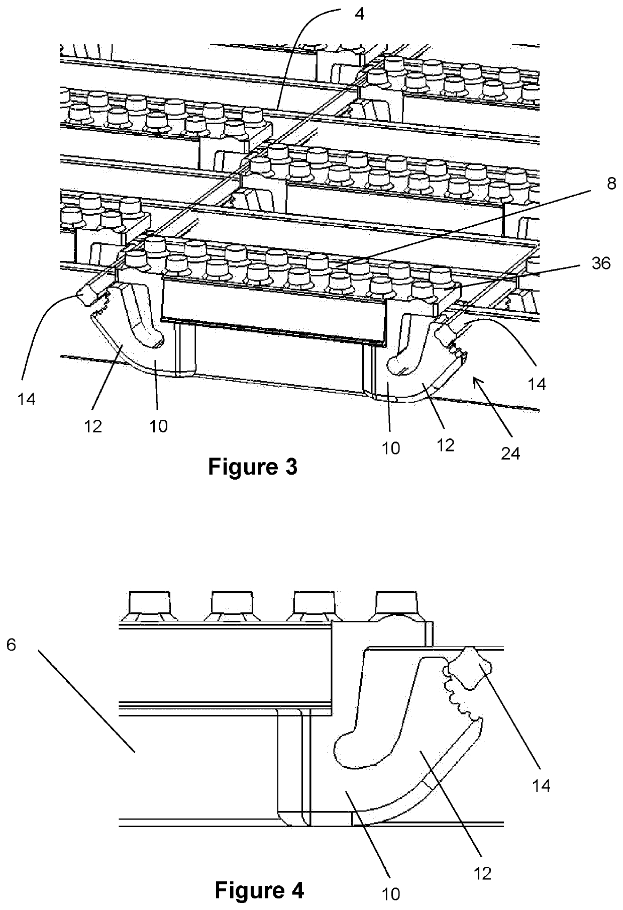
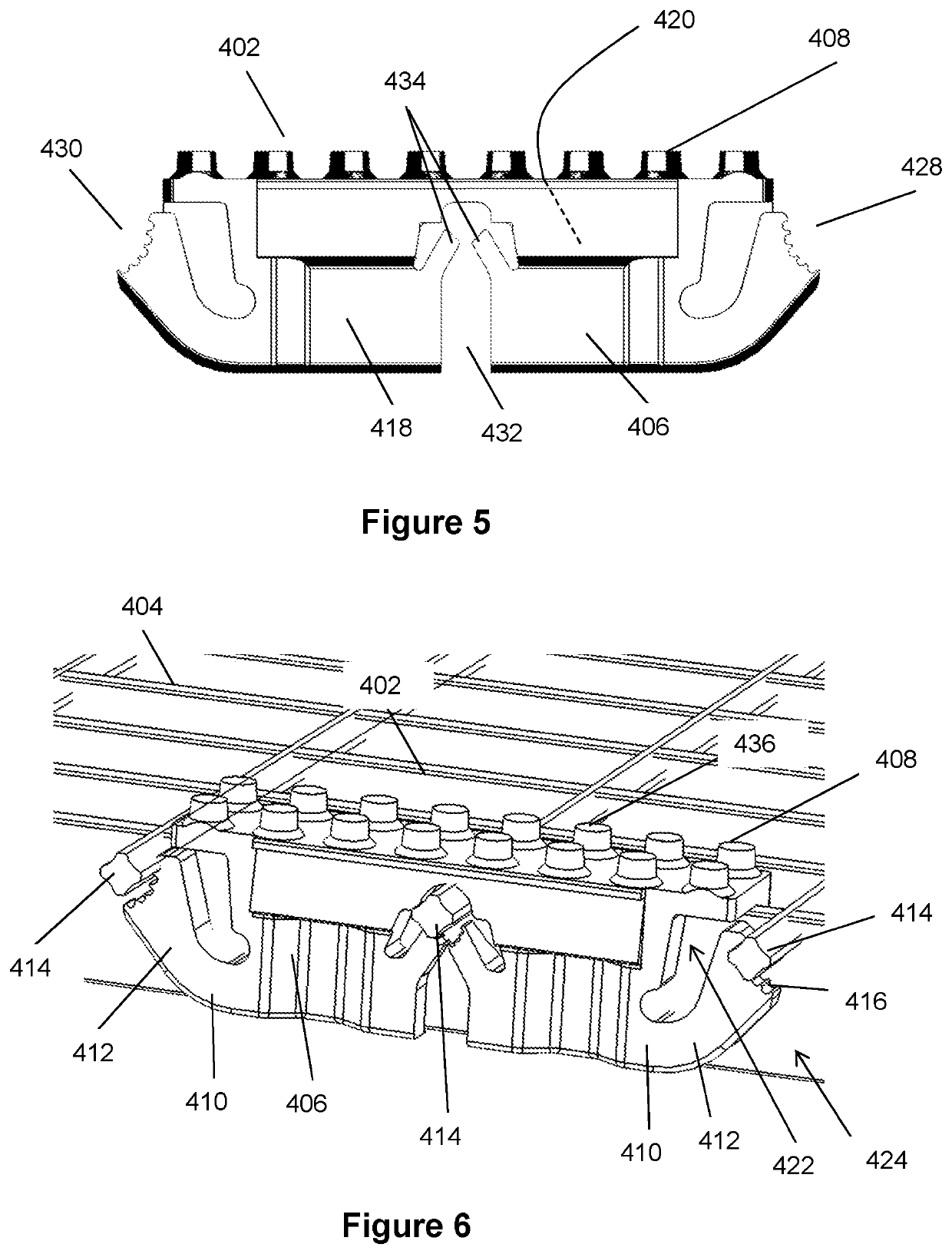
[0039]FIGS. 1 to 13 show seven versions of the attachment device. In each version shown, the device 2, 402, 502, 602, 702, 802, 902, 1002 has at least one point of flexure 10, 410, 510, 610, 710, 810, 910, 1010 with an arm 12, 412, 512, 612, 712, 812, 912, 1012 extending from the point of flexure 10, 410, 510, 610, 710, 810, 910, 1010, whereby the arm 12, 412, 512, 612, 712, 812, 912, 1012 is moveable about the point of flexure 10, 410, 510, 610, 710, 810, 910, 1010. Each version of the device 2, 402, 502, 602, 702, 802, 902, 1002 is able to be secured to a pathway (for example a grate shown in FIGS. 3, 6 and 11 as 4, 404, 804) through the engagement of the arms 12, 412, 512, 612, 712, 812, 912, 1012 with a component of the pathway.

[0040]FIGS. 1 to 4 and 7 show an embodiment of the attachment device 2 for attachment to a pathway 4 comprising a body 6 having: a top surface 8 for receiving foot traffic thereon. The embodiment of FIGS. 1 to 4 and 7 has four points of flexure 10, with e...


PUM

PropertyMeasurementUnit
potential movementaaaaaaaaaa
frictionaaaaaaaaaa
widthaaaaaaaaaa

Abstract

An attachment device for attachment to a pathway comprising a body having: a top surface for receiving foot traffic thereon; at least one point of flexure; and at least one arm extending from the point of flexure with the arm moveable about the point of flexure, the at least one arm configured to engage the pathway or a structural member of the pathway, wherein when engaged, the at least one arm secures the device to the pathway, wherein engagement of the at least one arm results in the device being compressively secured to the pathway in between two component members of the pathway.

Description

[0001]The present application claims priority from Australian Provisional Patent Application 2019900713 filed 5 Mar. 2019, the entire contents of which is incorporated herein by reference.TECHNICAL FIELD[0002]The invention relates to a safety device for attachment to a pedestrian or vehicle pathway surface, in particular a grating.BACKGROUND OF INVENTION[0003]The following discussion of background art is included to explain the context of the present invention. A reference herein to a matter which is given as prior art is not to be taken as an admission that the matter was known or that the information it contains was part of the common general knowledge as at the priority date of any of the claims.[0004]When designing and constructing pathways such as walkways, walking paths, footpaths, driveways and thoroughfares, there are minimum standards which must be adhered to. Depending on the purpose of the path or thoroughfare, these standards will often specify the load capacity, dimensi...

Claims


Application Information

Patent Timeline
Patent Type & Authority Applications(United States)
IPC IPC(8): E01C11/24E04C2/42E04F15/02E04F15/06E04F15/10
CPCE01C11/24E04C2/42E04F15/02172E01C9/10E04F15/06E04F15/105E04F2290/00E04F15/02183E06C7/081E04F19/10E04F11/17E01D19/125E01C17/00E01C5/226
Inventor LEROUX, ANDRE
Owner LEROUX ANDRE
Why Eureka
Try Eureka