Lid body and sealed battery

a technology of sealing material and battery body, which is applied in the direction of cell components, cell component details, electrochemical generators, etc., can solve the problems of difficult to prevent peeling at the joint surface of the sealing material and the terminal, and affect the performance of the battery, so as to reduce the number of parts used, reduce manufacturing costs, and reduce the sealing material sealability

Pending Publication Date: 2022-06-02
PRIME PLANET ENERGY & SOLUTIONS INC +1
View PDF2 Cites 0 Cited by
  • Summary
  • Abstract
  • Description
  • Claims
  • Application Information

AI Technical Summary

Benefits of technology

[0006]Attempts have been made in recent years to reduce the number of parts used in batteries, for the purpose of cutting manufacturing costs. For instance, an approach has been studied in which a terminal or sealing plate made of a metal is directly joined to a sealing material made up of a resin material, without using a component for joining the terminals by crimping. In the case of direct joining the sealing material and the terminal together, peeling at the joint surface therebetween may occur due to expansion or contraction of the component caused by changes in temperature. When peeling occurs at the joint surface, the sealability of the sealing material drops, which translates into impaired battery performance.

Problems solved by technology

When peeling occurs at the joint surface, the sealability of the sealing material drops, which translates into impaired battery performance.
Even if the mechanical strength of the sealing material is improved, it is, however, difficult to prevent peeling at the joint surface of the sealing material and the terminal due to expansion or contraction of the component caused by changes in temperature.

Method used


Image

  • Lid body and sealed battery
  • Lid body and sealed battery

Examples


example 1

[0053]Herein PPS and an inorganic filler were prepared to a ratio by weight of PPS:inorganic filler=90:10. Then PPS was melted at 330° C., and was mixed with an inorganic filler, to prepare an injection molding material.

[0054]There were prepared a 50 mm×50 mm×3 mm test pieces made of aluminum, and having a φ8 mm through-hole in the center. One of the surfaces of each test piece was subjected to a surface roughening treatment by laser irradiation.

[0055]A mold was prepared, for the surface of the test piece having undergone the surface roughening treatment, such that the through-hole of the test piece was plugged and such that a φ16 mm×3 mm injection molded body could be molded at the center of the test piece. The test piece was then placed in the mold.

[0056]A test molding material at 330° C. was filled in the mold at an injection rate of 50 mm / s.

[0057]Once the test molding material had cooled and hardened, the mold was removed, to yield Test sample example 1 in which a φ16 mm×3 mm mo...

examples 2 to 5

[0058]Test sample examples 2 to 5 were produced in the same way as in Test sample example 1, but herein the test molding material was prepared so that the mixing ratio of PPS and inorganic filler took on the values of ratio by weight given in Table 1.

Measurement of the Coefficient of Linear Expansion

[0059]The coefficients of linear expansion of the produced Test sample examples 1 to 5 were measured by TMA. The results are given in Table 1.

TABLE 1Test molding materialThermalweight percentCoefficient of linearcyclingTest samplePPSInorganic fillerexpansion × 10−5 / KresistanceExample 190101.8GoodExample 280202GoodExample 370302.3GoodExample 460403.5PoorExample 550505Poor

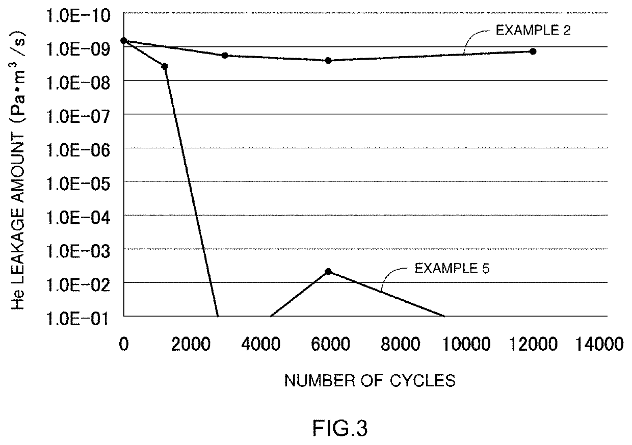
Thermal Cycling Test

[0060]Thermal cycling from −65° C. to 120° C. was carried out, over 5500 cycles, for Test sample examples 1 to 5.


PUM

PropertyMeasurementUnit
temperatureaaaaaaaaaa
pressureaaaaaaaaaa
breaking strengthaaaaaaaaaa

Abstract

Provided is a lid body including: a terminal member being mainly made up of a first metal; a sealing plate mainly made up of a second metal; and a sealing material. The sealing plate has a mounting hole for attaching the terminal member. The terminal member is inserted into the mounting hole and is attached to the sealing plate in a state where the sealing material is joined to a peripheral edge portion of the mounting hole. With as αS a coefficient of linear expansion at 25° C. of the sealing material, α1 as a coefficient of linear expansion at 25° C. of the first metal and α2 as a coefficient of linear expansion at 25° C. of the second metal, αL≤αS≤αH is satisfied, where αH is the higher value and αL is the lower value from among the α1 and α2.

Description

BACKGROUND OF THE INVENTION1. Field of the Invention[0001]The present disclosure relates to a lid body and to a sealed battery that utilizes the lid body. More specifically, the present disclosure relates to a lid body provided with a sealing material, and to a sealed battery that utilizes the same. The present application claims priority based on Japanese Patent Application No. 2020-198151 filed on Nov. 30, 2020, the entire contents whereof are incorporated in the present specification by reference.2. Description of the Related Art[0002]Nonaqueous electrolyte secondary batteries such as lithium ion secondary batteries have become increasingly important as vehicle-mounted power sources and power sources for personal computers and mobile terminals. In particular, lithium ion secondary batteries, which are lightweight and afford high energy densities, are preferably used as high-output power sources mounted on vehicles.[0003]Secondary batteries of this type are constructed, for instan...

Claims


Application Information

Patent Timeline
Patent Type & Authority Applications(United States)
IPC IPC(8): H01M50/167H01M50/15
CPCH01M50/167H01M50/15H01M50/176H01M50/188H01M50/198H01M50/193H01M50/184H01M10/0525H01M10/0587H01M50/159H01M50/562H01M50/172Y02E60/10
Inventor SATO, YUKIUCHIDA, YOZOASADACHI, HIDEKIEHARA, TSUYOSHITSUCHIYA, SYOICHIASAI, MASATAKAASANO, TSUYOSHIUCHIMURA, MASAHIROTATEYAMA, NOZOMI
Owner PRIME PLANET ENERGY & SOLUTIONS INC
Why Eureka
Try Eureka