
Systems, apparatuses, and methods for removing a medical implant from cardiac tissue

Pending Publication Date: 2022-06-02
EVALVE
View PDF0 Cites 1 Cited by
  • Summary
  • Abstract
  • Description
  • Claims
  • Application Information

AI Technical Summary

Benefits of technology

The patent text describes methods for repairing heart valves through minimally invasive procedures. The techniques involve using devices that are advanced through a patient's blood vessels to access the mitral valve and performing necessary repairs. The technical effects of this innovation include improved operative precision, reduced risks of complications and improved patient outcomes.

Problems solved by technology

Sometimes after such a device is installed in the heart, problems may still exist or could arise with the function of the mitral valve or with the heart generally.
However, less invasive methods would be preferable, because, for example, persons with a mitral valve fixation device may not be suitable candidates for invasive surgery.

Method used


Image

  • Systems, apparatuses, and methods for removing a medical implant from cardiac tissue
  • Systems, apparatuses, and methods for removing a medical implant from cardiac tissue
  • Systems, apparatuses, and methods for removing a medical implant from cardiac tissue

Examples


embodiment 1

[0141] An implant removal device including an elongate body and a capturing structure. The elongate body has a proximal end and a distal end. The elongate body is resiliently flexible and configured to transmit torque from the proximal end to the distal end with a predetermined turning ratio. The capturing structure extends distally from the distal end and has a capture region. The capturing structure is configured to selectively center a deployed implant in relation to a longitudinal axis of the elongate body and enclose the deployed implant.

[0142]Embodiment 2. The implant removal device of embodiment 1, wherein the capturing structure includes a braided conical structure having a trumpet curved convex shape or a straight conical shape.

[0143]Embodiment 3. The implant removal device of any of embodiment 1, wherein the capturing structure includes a finger conical structure.

[0144]Embodiment 4. The implant removal device of any of embodiments 1 and 3, wherein an angular orientation of...

embodiment 11

[0151] An implant removal device includes an implant management tool and an implant capturing device. The implant management tool is configured for use in selectively separating an implant from tissue to which the implant is attached. The implant management tool includes a distal opening with a cutting member configured to selectively extend from the distal opening to cut the tissue. The implant capturing device selectively extends from the distal end of the implant management tool. The implant capturing device includes an elongate body and a capturing structure. The elongate body has a proximal end and a distal end. The elongate body is resiliently flexible. The capturing structure extends distally from the distal end of the elongate body and has a capturing region. The capturing structure is configured to selectively center a deployed implant in relation to a longitudinal axis of the elongate body and encloses the employed implant.

[0152]Embodiment 12. The implant removal device of...

embodiment 13

[0153] The implant removal device of any of embodiments 11-12, wherein the cutting member is disposed within the shaft.

[0154]Embodiment 14. The implant removal device of any of embodiments 11-13, wherein the implant capturing device is slidably disposed within a lumen of the cutting member.

[0155]Embodiment 15. The implant removal device of any of embodiments 11-14, wherein the cutting member is configured to slide along the implant capturing device and collapse the capturing structure.

[0156]Embodiment 16. The implant removal device of any of embodiments 11-15, wherein the capturing structure includes a braided conical structure having a trumpet curved convex shape or a straight conical shape.


PUM


Abstract

An implant removal device having an elongate body having a proximal end and a distal end, the elongate body being resiliently flexible and configured to transmit torque from the proximal end to the distal end with a predetermined turning ratio, and a capturing structure extending distally from the distal end and having a capture region, the capturing structure being configured to selectively center a deployed implant in relation to a longitudinal axis of the elongate body and the capture region to aid with capture and subsequent removal.

Description

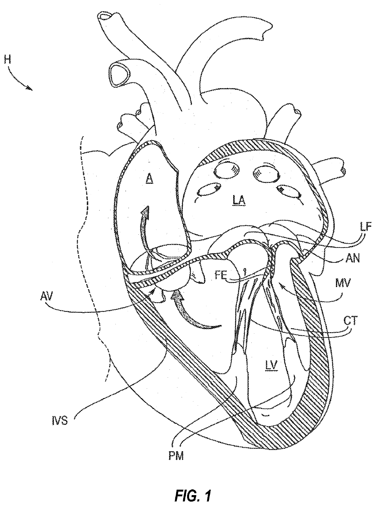
CROSS-REFERENCE TO RELATED APPLICATIONS[0001]This application claims benefit of and priority to U.S. Patent Application No. 63 / 119,317, filed Nov. 30, 2020, the entire contents of which are incorporated by reference herein.BACKGROUND OF THE INVENTION1. The Field of the Invention[0002]The present disclosure relates generally systems, apparatuses, and methods for removal of a medical implant from cardiac tissue, such as a medical implant attached to a valve leaflet.2. The Relevant Technology[0003]The present invention relates generally to medical methods, devices, and systems. In particular, the present invention relates to methods, devices, and systems for the endovascular, percutaneous, or minimally invasive surgical treatment of bodily tissues, such as tissue approximation or valve repair. More particularly, the present invention relates to repair of valves of the heart and venous valves, and devices and methods for removing or disabling mitral valve repair components through minim...

Claims


Application Information

Patent Timeline
IPC IPC(8): A61B17/34A61B17/00
CPCA61B17/3468A61B2017/00867A61B2017/00243A61B17/00234A61F2/246A61F2/2463A61F2/2466A61F2002/9528A61B2017/2215A61B17/221
Inventor DALE, THEODORE PAULEIDENSCHINK, TRACEE ELIZABETH JOHNSON
Owner EVALVE
Learn More