A scope
a technology of scope and otoscope, which is applied in the field of scope, can solve the problems of affecting the outcome of surgery, poor visualization of disease in difficult to access areas in the middle ear, and invasive ear surgery, so as to reduce the admission time, improve the outcome, and reduce the complication rate
- Summary
- Abstract
- Description
- Claims
- Application Information
AI Technical Summary
Benefits of technology
Problems solved by technology
Method used
Image
Examples
first embodiment
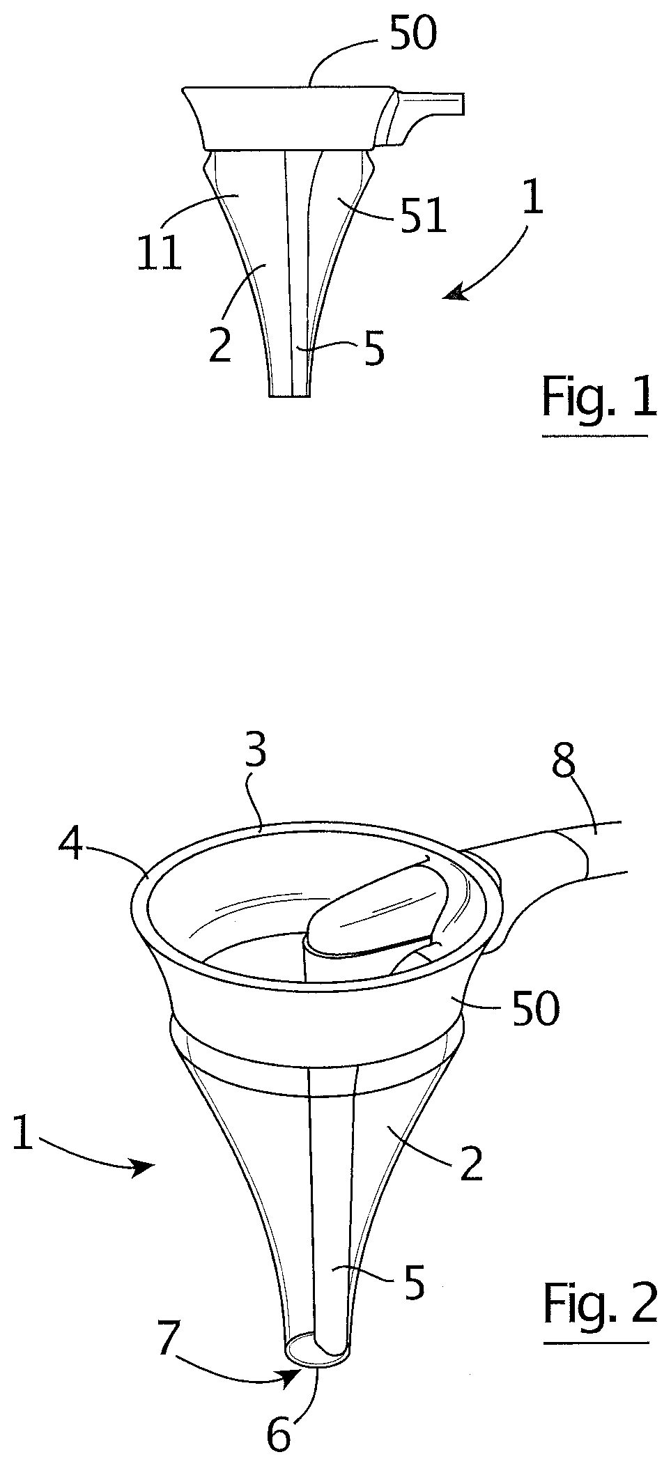
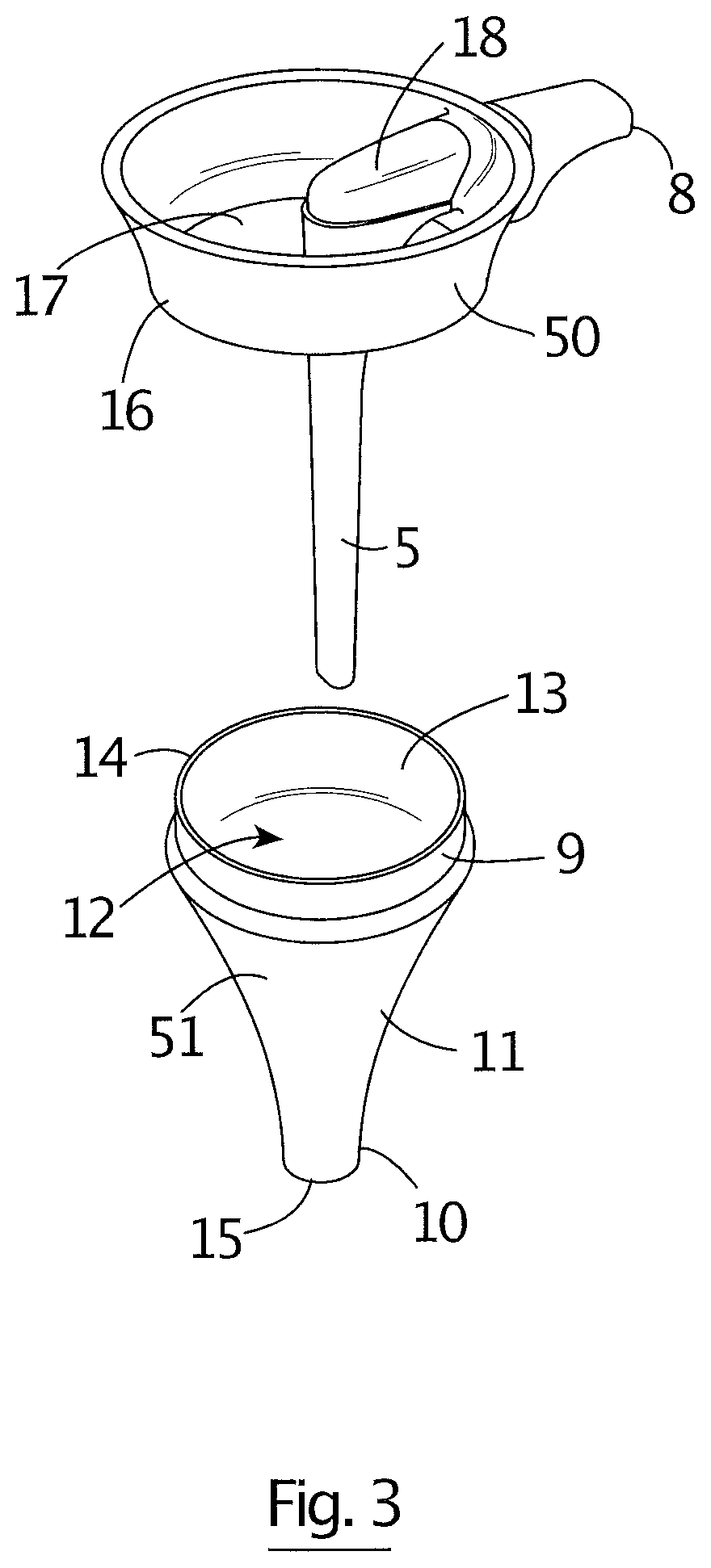
[0202]As shown in FIGS. 1 to 3 of the accompanying drawings, a scope of the invention is generally indicated by the reference numeral 1 and has a stabilizer 2 made up of a speculum holder 50 and a speculum 51 attached to the speculum holder 50. The speculum holder 50 can be in the form of a speculum handle 3 defining a collar 4 for receiving and holding the speculum 51. The scope 1 also has a flexible or rigid integrated elongate probe 5 attached to the collar 4 and located in the speculum 51. The probe 5 is fitted with at least one camera 6 and a light source 7 for visualising the ear and is preferably formed from materials that allow the probe 5 to have a low mass. A data cable 8 extends from the probe 5 via the collar 4 to a display (not shown) to display images from the camera 6.
[0203]The stabilizer 2 is configured to stabilize the device in an ear canal in use. More particularly, as the probe 5 is integrated with the stabilizer 2 in a unitary scope and stabilizer structure, a c...
second embodiment
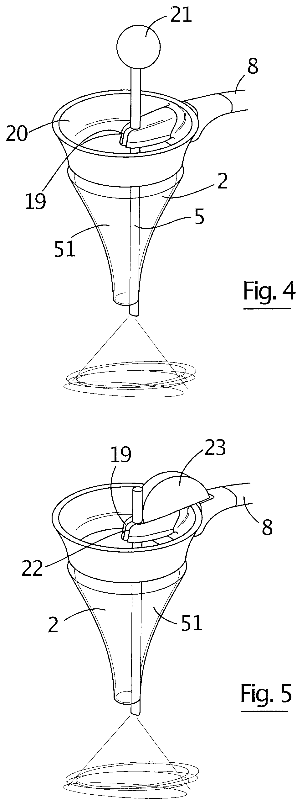
[0209]FIG. 4 shows a perspective view from above and one side of the scope 1 similar to the scope 1 of FIGS. 1 to 3 but in which the elongate probe 5 is slidably mounted on the speculum 51. Like numerals indicate like parts. More particularly, the elongate probe 5 is slidably mounted on the collar 4 at a probe moving mechanism 19. The probe moving mechanism 19 an encompass any suitable form of movement which allows for movement of the probe 5 e.g. proximal or distal movement of the probe 5. In the present embodiment, the probe moving mechanism 19 is a probe sliding or translating mechanism 19 so that the elongate probe 5 can be slidably inserted through and slidably removed from the speculum 2 as required. Accordingly, the elongate probe 5 can slidably project from the narrow insertion opening 15 as required in use to facilitate enhanced visualisation of the ear as shown in the drawing.
[0210]In the present embodiment, the sliding mechanism 19 is in the form of friction fit / mounting ...
third embodiment
[0214]FIG. 7 is a side elevation of the scope 1 in which, in addition to the elongate probe 5 being slidable, the elongate probe 5 is curved to conform with at least a portion of the contour of the wall 11 of the speculum 51 to create additional space in the speculum chamber 12 for a surgeon in use. The scope 1 is provided with a depth control actuator 21 in the form of a wheel 28.
[0215]FIG. 8 is a side elevation of the endoscope of FIG. 7 but in which the depth control actuator 21 is in the form of a slider 29 on a grip 25.
PUM
 Abstract
Description
Claims
Application Information
 - R&D
- Intellectual Property
- Life Sciences
- Materials
- Tech Scout
- Unparalleled Data Quality
- Higher Quality Content
- 60% Fewer Hallucinations
Browse by: Latest US Patents, China's latest patents, Technical Efficacy Thesaurus, Application Domain, Technology Topic, Popular Technical Reports.
© 2025 PatSnap. All rights reserved.Legal|Privacy policy|Modern Slavery Act Transparency Statement|Sitemap|About US| Contact US: help@patsnap.com


