
Heat exchanger

a heat exchanger and brazed plate technology, applied in the direction of heat exchange apparatus, heat exchanger fastening, stationary plate conduit assembly, etc., can solve the problems of large force required to press the plate, and high cost of presses, etc., and achieve the effect of high “nip force”

Pending Publication Date: 2022-05-19
SWEP INT
View PDF0 Cites 0 Cited by
  • Summary
  • Abstract
  • Description
  • Claims
  • Application Information

AI Technical Summary

Benefits of technology

[0011]Preferably the heat exchanger plates are made from austenitic stainless steel having a thickness of 0.1 to 2 mm, since such a thickness will give the required strength while enabling low cost production.
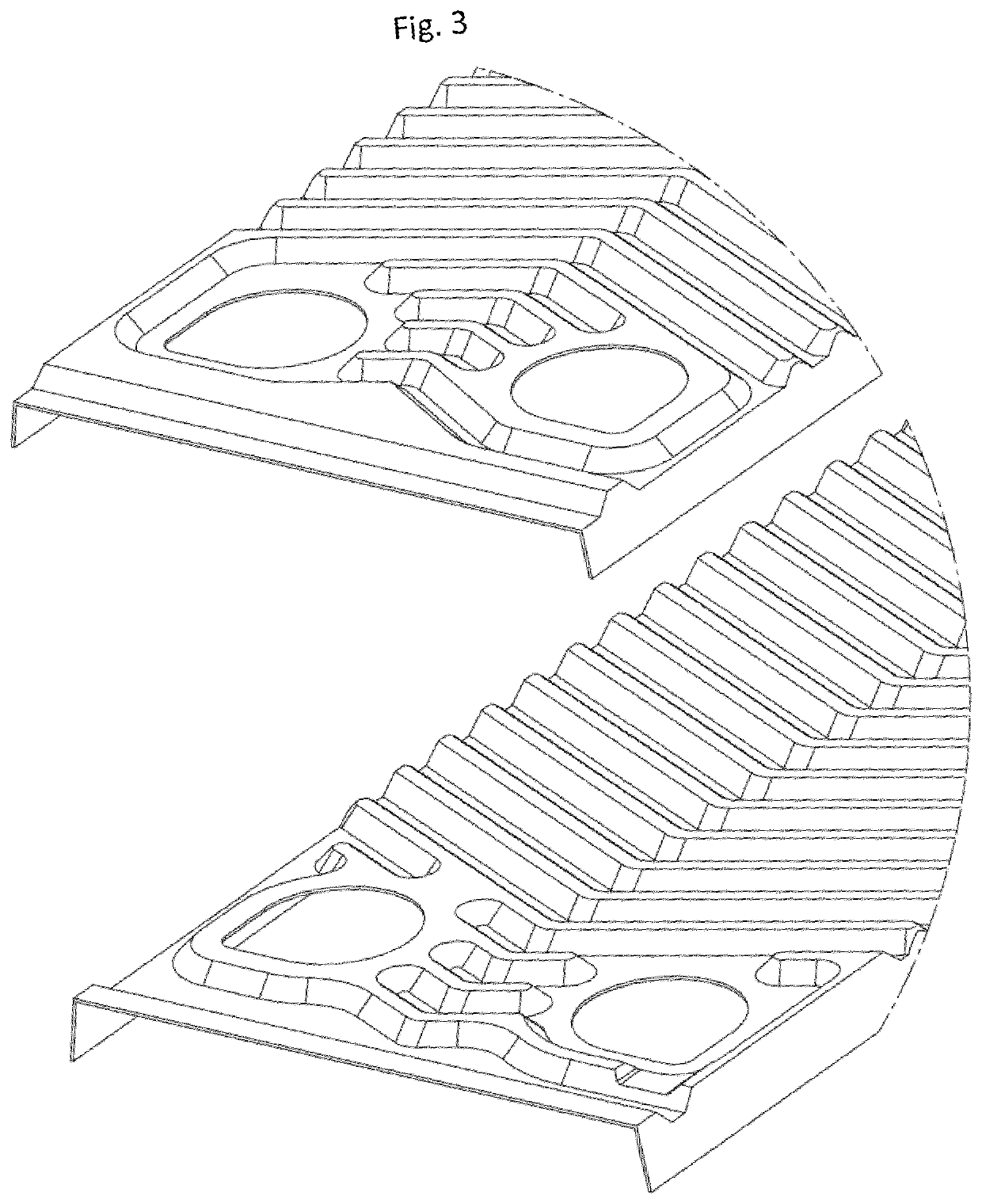
[0014]In one embodiment of the invention, the skirts that extend at least partly along the long sides of the heat exchanger plates are arranged close to perpendicular relative to a plane of the heat exchanger plates, such that skirts of neighboring plates will contact one another in an overlapping fashion and after brazing provide a seal for the interplate flow channels. This embodiment is beneficial in that it gives a heat exchanger with an efficient heat transfer.
[0015]In one embodiment of the invention, the flat seal along the short ends of the heat exchanger plates is provided by elongate areas adapted to contact one another in the same fashion as areas surrounding the port openings contact one another in order to provide for the selective communication between the port openings and the interplate flow channels. This embodiment is beneficial in that the lateral distribution of fluids will be efficient and in that the heat exchanger plates may be manufactured by roll forming.
[0019]In one embodiment of the invention, the heat exchanger plates are manufactured by roll forming. This embodiment is beneficial in that roll forming provides for a cost and energy efficient way of manufacturing heat exchanger plates.
[0024]In one embodiment of the method, one of the rolls may be powered and the other may rotate freely. This embodiment is beneficial in that a minimal amount of stress will be induced in the pressed plate by the roll forming operation.
[0026]In still another embodiment of the invention, the rolls may have different diameters. This is beneficial in that a high “nip force” may be achieved while having at least one large diameter roll.

Problems solved by technology

This solution is, however, uncommon, mainly due to the fact that this solution will give flow channels that have lateral channels where no heat exchange will take place.
Although pressing of the heat exchanger plates in one single operation gives a satisfactory result, it is not free from problems: First, the force necessary to press the plate becomes very large if the plates are large (pressing forces of several thousands of tons are not unusual), which requires large presses which are expensive and consume much electrical power.
By roll forming, it has, hitherto not been possible to provide the heat exchanger plates with circumferential skirts, but only circumferential sealing surfaces adapted to be flat brazed to similar surfaces of neighbouring plates.
As mentioned above, heat exchangers provided with such surfaces are less efficient than heat exchangers sealed by overlappingly interacting circumferential skirts, due to the shirt-circuiting straight channel with nor heat exchange inevitably being formed for one of the channels.

Method used


Image

  • Heat exchanger
  • Heat exchanger
  • Heat exchanger

Examples


Embodiment Construction

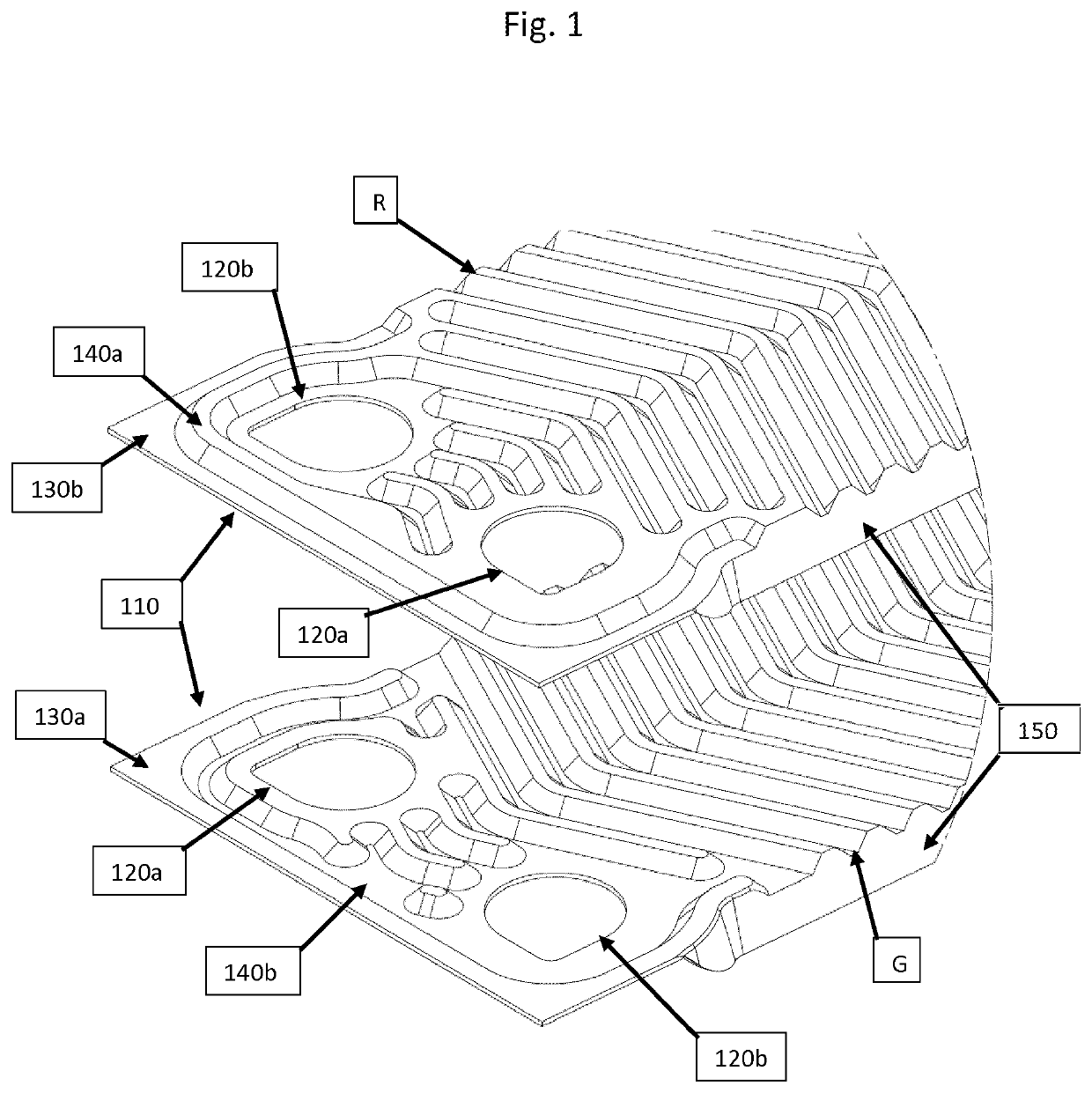
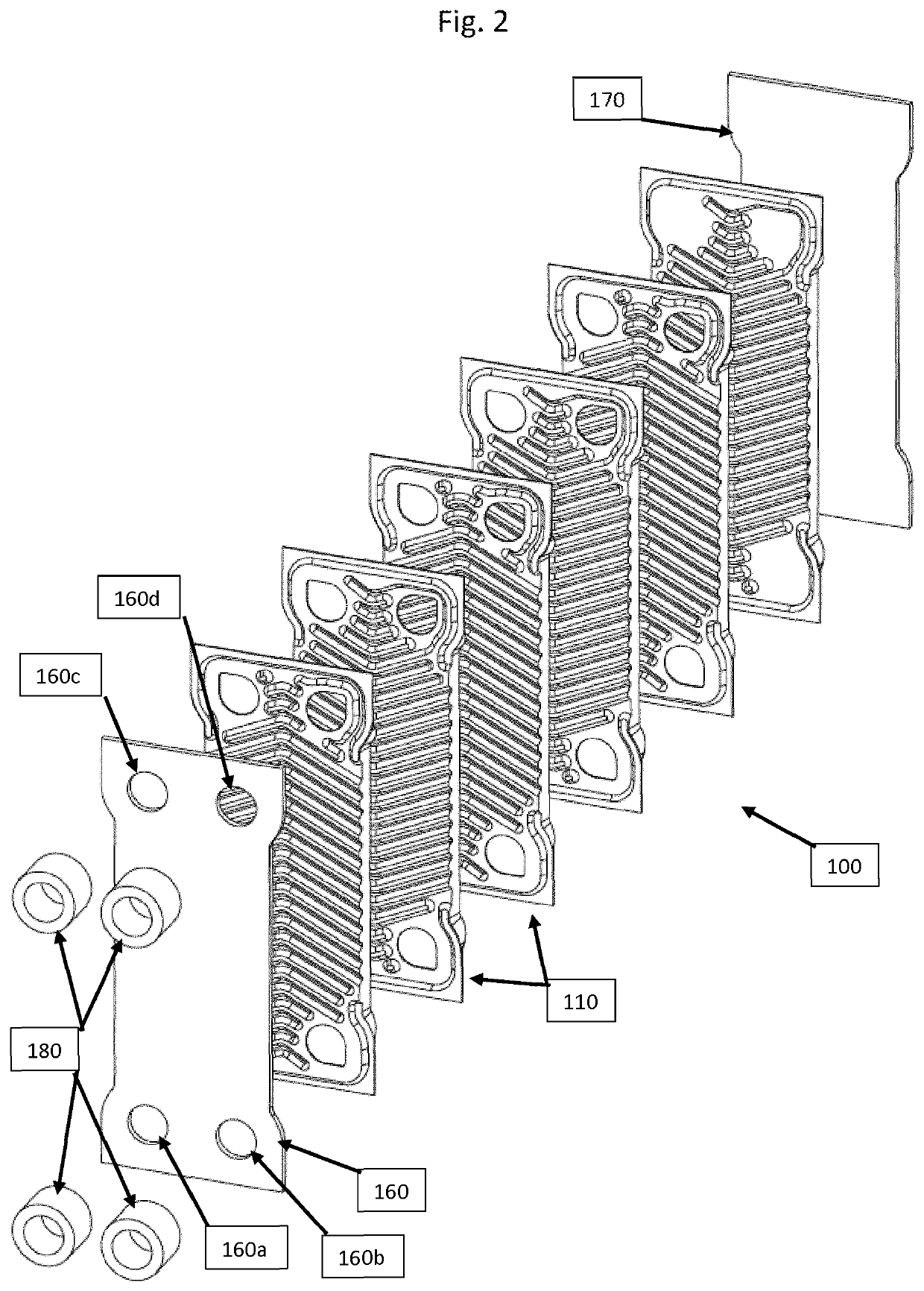
[0033]In FIG. 1, short ends of two heat exchanger plates 110 are shown. The heat exchanger plates 110 may be made from e.g. austenitic stainless steel in a thickness of 0.1 to 2 mm, but may also be made from other materials in other thicknesses. The short ends each comprise two port openings 120a and 120b, wherein the port openings 120a are provided on a high level and the port openings 120b are provided on a low level. The short ends of each heat exchanger plate 110 are not similar. Rather, sealing surfaces 130a, 130b, and 140a, 140b, respectively, and areas surrounding the port openings 120a, 120b are mirror images of one another. The sealing surface 130b, the sealing surface 140b and the area surrounding the port openings 120b are located on a low level, whereas the sealing surface 130a, the sealing surface 140a and the areas surrounding port openings 120a are located on a high level.

[0034]When the heat exchanger plates 110 are stacked in a stack to form a heat exchanger, every o...


PUM

PropertyMeasurementUnit
thicknessaaaaaaaaaa
thicknessesaaaaaaaaaa
lengthaaaaaaaaaa

Abstract

A brazed plate heat exchanger (100) for exchanging heat between at least two fluids comprises several elongate heat exchanger plates (110) provided with a pressed pattern comprising depressions and elevations adapted to keep the plates on a distance from one another by contact points between the elevations and depressions of neighboring plates under formation of interplate flow channels for media to exchange heat. At least four port openings are placed in corner regions of the elongate heat exchanger plates and have selective fluid communication with the interplate flow channels such that the fluids to exchange heat will flow between port openings parallel to long sides of the elongate heat exchanger plates. A circumferential seal sealing off the interplate flow channels from communication with the surroundings is provided, and the heat exchanger plates are joined by brazing. The circumferential seal results partly from contact between skirts of neighboring plates contacting one another, said skirts extending at least partly along two sides of each heat exchanger plates, and partly from contact between flat areas extending along two other sides of the heat exchanger plates.

Description

CROSS-REFERENCE TO RELATED APPLICATIONS[0001]This application is a divisional of U.S. application Ser. No. 16 / 770,057, filed 4 Jun. 2020, which is a U.S. National Stage Application of PCT / EP2018 / 083553, filed 4 Dec. 2018, which claims benefit of Ser. No. 17 / 51497-7, filed 5 Dec. 2017 in Sweden and which applications are incorporated herein by reference. To the extent appropriate, a claim of priority is made to each of the above disclosed applications.FIELD OF THE INVENTION[0002]The present invention relates to a brazed plate heat exchanger for exchanging heat between at least two fluids, the heat exchanger comprising several elongate heat exchanger plates provided with a pressed pattern comprising depressions and elevations adapted to keep the plates on a distance from one another by contact points between the elevations and depressions of neighboring plates under formation of interplate flow channels for media to exchange heat, at least four port openings being placed in corner reg...

Claims


Application Information

Patent Timeline
Patent Type & Authority Applications(United States)
IPC IPC(8): F28D9/00F28F3/04
CPCF28D9/005F28F3/10F28F3/046F28F2275/04B21D13/04B21D53/04B21H8/005B21H8/02F28F21/083F28F2230/00F28F3/025Y10S165/382
Inventor DAHLBERG, TOMASANDERSSON, SVEN
Owner SWEP INT
Learn More