
A system for manufacturing last-based equipment for direct injection production of footwear and a method for manufacturing footwear

a manufacturing equipment and technology for footwear, applied in the field of system for manufacturing equipment for direct injection production of footwear, can solve the problems of time-consuming and expensive methods of preparing moulds, equipment needed is relatively expensive, and production may require a relatively long running-in period, so as to achieve easy and less costly local manufacture, the effect of reducing production costs

Pending Publication Date: 2022-05-19
ECCO SKO
View PDF0 Cites 0 Cited by
  • Summary
  • Abstract
  • Description
  • Claims
  • Application Information

AI Technical Summary

Benefits of technology

This patent describes a method to make footwear faster and more cost-efficiently by using a last that can be easily made and discarded instead of returning it for correction. This saves time and money as there is no need to transport the last to a different location. Additionally, the heat transfer between the mold and the inserts is improved, resulting in better conditions for direct injection molding of the footwear sole.

Problems solved by technology

The methods of preparing moulds are time consuming and expensive as the equipment needed are relatively expensive.
The production may require a relatively long running-in period, e.g. due to the respective locations being located away from each other and due to the time-consuming transports of the respective tools, e.g. moulds and lasts, possibly enlarged by any necessary corrections to the equipment.
Furthermore, the costs involved in a start-up of a new footwear design may thus be relatively large.

Method used


Image

  • A system for manufacturing last-based equipment for direct injection production of footwear and a method for manufacturing footwear
  • A system for manufacturing last-based equipment for direct injection production of footwear and a method for manufacturing footwear
  • A system for manufacturing last-based equipment for direct injection production of footwear and a method for manufacturing footwear

Examples


Embodiment Construction

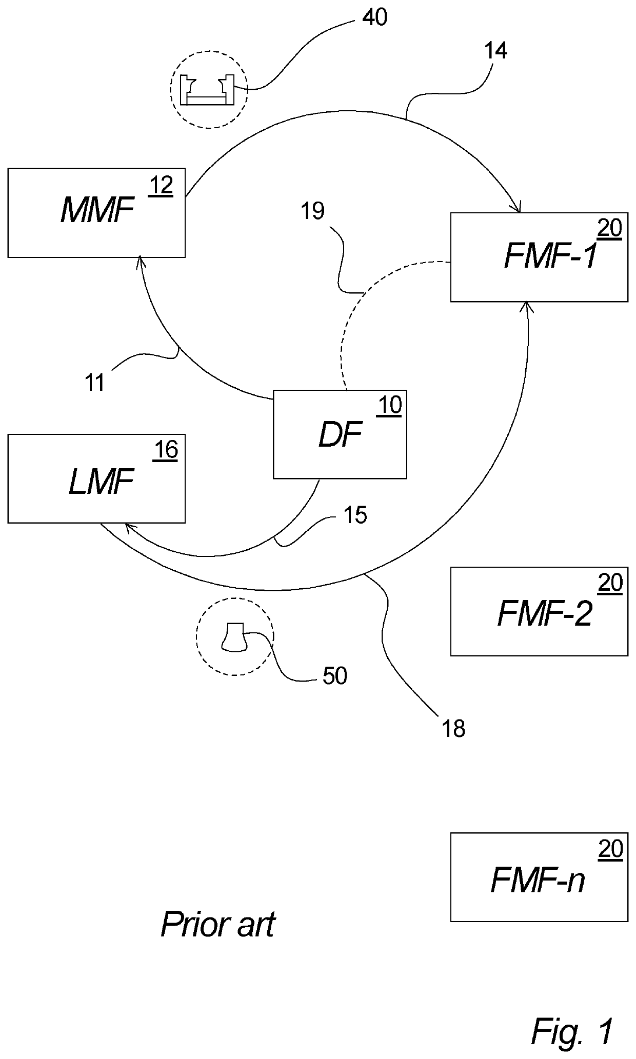
[0188]In FIG. 1 a system for production of footwear is illustrated, wherein the illustrated system includes manufacturing of tooling for production of footwear as it takes place in connection with a prior art system.

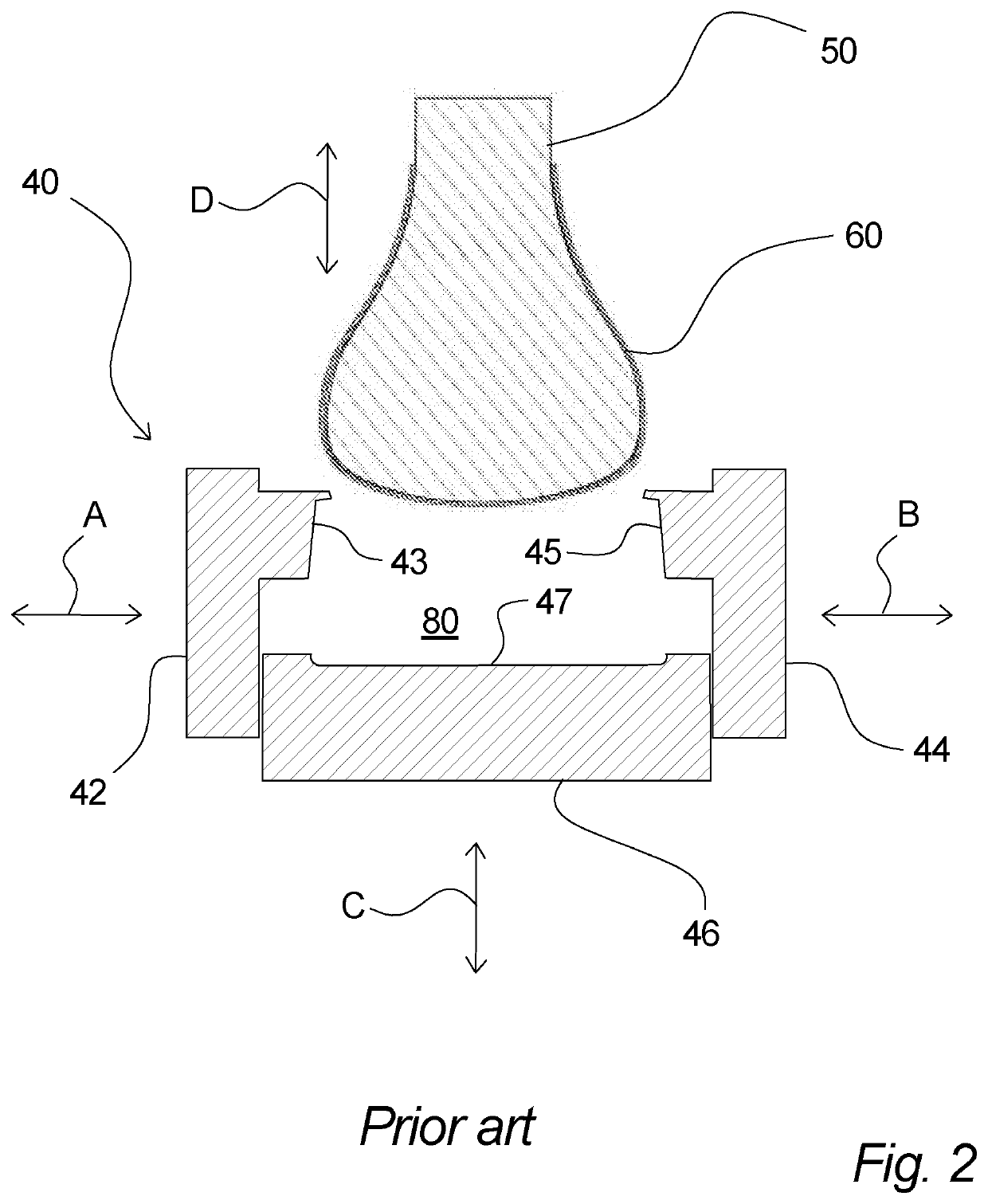
[0189]A design facility (DF) 10, which is located at a design facility location, provides a footwear design, e.g. when a new type, a new design, etc. of a shoe is to be made. In connection with a direct injection production (DIP) process, wherein a shoe upper is placed on a last, wherein the last with the shoe upper is placed into a mould and wherein subsequently a liquid sole material such as for example liquid polyurethane (PU) is injected into the mould to effect a strong attachment of the upper to the sole, a last and a mould must be provided, corresponding to the specific footwear design.

[0190]The manufacture of moulds and lasts are typically specialized jobs and are typically made by specialized entities, e.g. due to the required knowledge and skills, and thus, the...


PUM

PropertyMeasurementUnit
height h1aaaaaaaaaa
height h2aaaaaaaaaa
height h2aaaaaaaaaa

Abstract

A system for manufacturing equipment for a direct injection production of footwear. The equipment includes molds for direct injection production of footwear. The system includes a design facility that provides a footwear design. A mold manufacturing facility located manufactures a mold corresponding to the footwear design. The mold is for direct injection molding of a sole part of the footwear. At least one footwear manufacturing facility manufactures footwear according to the footwear design, utilizing a last corresponding to the footwear design and the mold corresponding to the footwear design. Last descriptive data relating to said last corresponding to said footwear design is provided. The last descriptive data is communicated to the footwear manufacturing facility for manufacturing the last at the footwear manufacturing location or the last is manufactured at a last manufacturing facility, based on last descriptive data, and transported to the footwear manufacturing facility.

Description

FIELD OF THE INVENTION[0001]The Invention relates to a system for manufacturing equipment for a direct injection production (DIP) of footwear.BACKGROUND OF THE INVENTION[0002]Shoe manufacturing is often a mass production process that involves customized equipment for the production.[0003]The shoe sole can be attached to an upper by e.g. direct injection moulding where the injection moulds conventionally are manufactured from e.g. aluminium that may be CNC cut to define mould cavity. The methods of preparing moulds are time consuming and expensive as the equipment needed are relatively expensive. Furthermore, designing new lines of shoe often involves a plurality of adjustments before the finished shoe line is ready for production and herein each size and orientation of the shoe needs a separate mould.[0004]Preparing equipment e.g. moulds for shoe production is conventionally a process involving several locations e.g. a design facility providing a footwear design, a last manufacturin...

Claims


Application Information

Patent Timeline
Patent Type & Authority Applications(United States)
IPC IPC(8): B29D35/00B33Y80/00B29D35/12A43D3/02
CPCB29D35/0027B29D35/0036B33Y80/00B29K2075/00B29D35/128A43D3/02B29D35/122B29D35/0045A43D1/02B33Y50/02B22F2998/10B29C45/14065B29C45/2673B29C45/33B29C45/36B29L2031/50B29C45/0001B29C45/0084Y02P10/25B22F10/18B22F10/28B22F10/12B22F10/14B22F3/10
Inventor HANSEN, JAKOB MOLLERMORTENSEN, JENS SONNE
Owner ECCO SKO
Learn More