Systems and methods for producing ice

a technology of ice production and production methods, applied in the field of high-quality ice making, can solve the problems of simple molds, low quality of ice that comes out, and inconvenient use, and achieve the effects of reducing thermal resistance, reducing heat loss, and reducing was

Pending Publication Date: 2022-05-12
NICELABS LLC
View PDF4 Cites 1 Cited by
  • Summary
  • Abstract
  • Description
  • Claims
  • Application Information

AI Technical Summary

Benefits of technology

[0024]An ice machine in accordance with the principals of the present invention provides a thermal transfer surface directly coupled with a side of a tray leading to faster and more consistent ice growth. An ice machine in accordance with the principals of the present invention provides trays that are optimized (material and / or geometry) to minimize thermal resistance. An ice machine in accordance with the principals of the present invention provides uniform ice forms with no parting lines or gate marks. An ice machine in accordance with the principals of the present invention provides a protection from freezer burn. An ice machine in accordance with the principals of the present invention prevents ice from being sintered together. An ice machine in accordance with the principals of the present invention utilizes a velocity profile at the water / ice boundary layer to yield a substantially clear ice form with a lower concentration of impurities such as total dissolved solids (TDS) and total dissolved gasses (TDG) than the initial water placed in the system. An ice machine in accordance with the principals of the present invention can provide a cost effective, compact ice machine that creates a consistent and pleasant ice harvesting experience for the customer.
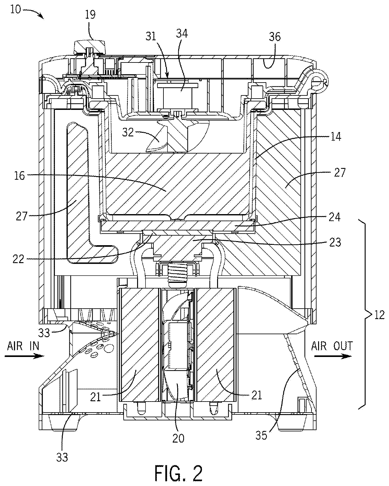
[0025]In accordance with the principals of the present invention, an ice machine, tray, and process for producing high-quality, substantially clear ice is provided. A heat exchanger in the ice machine removes energy from liquid, cooling the liquid from room temperature to freezing temperature, then overcomes the heat of fusion to form ice. The tray containing a liquid is received in a freezing / mixing chamber. The tray includes an energy transfer surface in thermal contact with the heat exchanger to define a liquid / ice boundary layer. The tray further includes at least one freezing cavity having geometry defining surfaces to form the geometry of the ice. An egress area is defined in the tray above the geometry defining surfaces. A mixing mechanism is provided in operative communication with the liquid to create a velocity profile at the liquid / ice boundary layer to create a directional freezing process starting from the energy transfer surface of the tray in thermal contact with the heat exchanger and growing through the freezing cavity up to the egress area. The velocity profile at liquid / ice boundary enables impurities to be washed away during the freezing process, deterring impurities from getting entrapped in the ice. Impurities in the liquid are thereby encouraged to be washed away and concentrate in a pool away from the ice, ultimately in the egress area of the tray to be purged. In addition, in embodiments sensors can be provided to provide various functions selected from the group consisting of, for example, determining ice creation status, determining freezing height, varying ice creation, determining tray presence, detecting freezing / mixing chamber door position, determining liquid level, and combinations thereof.

Problems solved by technology

Large clear ice forms can ameliorate both problems.
Crystal clear ice making devices available today produce clear ice primarily using one of three methods, each with their own drawbacks: One is the use of simple molds, made of silicone, other plastic, and / or metal.
The main downfall of the use of simple molds is the quality of ice produced.
Not only are the final ice forms not clear, but the low quality of the water put in results in a low quality of the ice that comes out.
In addition, exposure of the top can result in freezer burn if left in too long without a cover.
Simple molds also take up valuable freezer space, can easily be spilt when transferring into or closing the freezer, can create ice forms that are unsymmetrical due to inadequate wall thicknesses, and have slow and inconsistent growth rates since the freezing is beholden to the air temperature and performance of the refrigeration system.
This solution does not deliver the premium ice and experience people deserve.
Although ice can be created with better transparency and lower TDS / TDG than simple molds, ice made utilizing these complex molds takes longer to form, takes up significantly more room in the freezer, and can still exhibit freezer burn on top if not properly covered.
Use of complex molds also makes ice harvesting cumbersome for the user.
The user must guess the best time to remove the system from the freezer: If they remove it too soon, the ice may not be fully formed, and they have to start over; if they remove it too late, the water reservoir below the mold can freeze, making it difficult to remove the mold and ice below.
In many instances customers have broken their assemblies during this process.
Although use of complex molds is relatively cheap and creates better ice than a simple mold, this attempted solution does not deliver the premium ice and experience people desire.
Attempts such as filtering water, heating / boiling water, degassing water, and many others have been tried; however, the same issues persist.
First, if a user just wants the ice making capabilities of system, they are required to purchase the whole refrigerator which is very large and expensive (industrial or other).
Like the mold solutions, the growth rate relies on cold air to transfer energy out of the water, which leads to long ice growth times (18-30 hours).
These ice machines also have the same drawbacks of the quality of the water placed in the tray will remain the same in the ice.
Although storage can be convenient, the ice forms could sinter together, making them difficult to remove.
The temperature at which a typical freezer is held at is also not ideal for clear ice.
The openness of the storage container could also lead to freezer burn on the ice forms.
Most units use refrigeration systems which are energy efficient but can take up significant space.
High throughput units, typically undercounter or stand alone, are a very expensive capital expense and typically require yearly service contracts.
The countertop solutions are medium cost and take up a good amount of counter space while producing sub-par ice using water filled by the user.
These are not meant for at home use due to size and cost (high to industrial range).
Aside from cost and size being a deterrent to consumers, these ice machines also require yearly servicing and professional installation for water and purge lines.
Also, during the harvesting stage, the quick change from cold to hot can crack the ice.
This ice making machine is also large and expensive, has low throughput and limited shape, and requires post processing.
Although the block ice machine has a high average throughput, each cycle requires one to three days due to the large ice forms created.
In addition, block ice machines can be up to 10 inches (25 centimeters) in height, resulting in less energy removed from the system over time, resulting in poor efficiency.
Still further, block ice machines need dedicated space, so much that restaurants and bars rarely have one onsite.
From a fixed cost perspective, block ice machines and their complementary post processing equipment cost thousands of dollars.

Method used


Image

  • Systems and methods for producing ice
  • Systems and methods for producing ice
  • Systems and methods for producing ice

Examples


embodiments / improvements

Possible Future Embodiments / Improvements

[0174]In addition to the process considerations in designing ice machines in accordance with the principals of the present invention, implementations can employ additional elements and improvements. For example, a water reservoir could be integrated into the ice machine but removeable by the user. The user could fill up this reservoir and install in the ice machine. Then the ice machine could pump and / or direct water from the reservoir into the tray. This could help reduce process variability, allowing for a consistent fill each time with no need for water sensing or intervention by the user.

[0175]The output of a process of the present invention is not only clear ice, but also water concentrated with impurities (TDS and TDG) that must be purged. In the exemplary embodiment described herein, the user must take the tray and dump out the water to retrieve their ice. Alternatively, the ice machine could automatically remove the water from the tray...


PUM


Abstract

In accordance with the principals of the present invention, an ice machine, tray, and process for producing high-quality, substantially clear ice is provided. A heat exchanger in the ice machine removes energy from liquid, cooling the liquid from room temperature to freezing temperature, then overcomes the heat of fusion to form ice. The tray containing a liquid is received in a freezing / mixing chamber. The tray includes an energy transfer surface in thermal contact with the heat exchanger to define a liquid / ice boundary layer. The tray further includes at least one freezing cavity having geometry defining surfaces to form the geometry of the ice. An egress area is defined in the tray above the geometry defining surfaces. A mixing mechanism is provided in operative communication with the liquid to create a velocity profile at the liquid / ice boundary layer to create a directional freezing process starting from the energy transfer surface of the tray in thermal contact with the heat exchanger and growing through the freezing cavity up to the egress area. The velocity profile at liquid / ice boundary enables impurities to be washed away during the freezing process, deterring impurities from getting entrapped in the ice. Impurities in the liquid are thereby washed away and concentrate in a pool away from the ice, ultimately in the egress area of the tray to be purged. In addition, in embodiments sensors can be provided to provide various functions selected from the group consisting of, for example, determining ice creation status, determining freezing height, varying ice creation, determining tray presence, detecting freezing / mixing chamber door position, determining liquid level, and combinations thereof.

Description

CROSS-REFERENCE TO RELATED APPLICATIONS[0001]This utility patent application claims the benefit of and priority to U.S. Provisional Patent Application No. 63 / 110,611, filed 6 Nov. 2020, also entitled “Systems and Methods for Producing Ice”, the content of which is hereby incorporated by this reference.FIELD OF THE INVENTION[0002]The present invention relates to high-quality ice making.BACKGROUND OF THE INVENTION AND STATE OF THE ART[0003]There are many ice making technologies today that exist to create particular ice forms for specific market needs. Standard ice cubes are opaque and can melt quickly in beverages resulting in a warm drink with a watered-down taste. Large clear ice forms can ameliorate both problems. As used herein, the focus will be on technologies that aim to make substantially clear ice forms. Ice making technologies can be measured against key metrics, which include ice growth, ice shape / form, ice quality, machine price and size, and ease of use.[0004]Ice growth r...

Claims


Application Information

Patent Timeline
Patent Type & Authority Applications(United States)
IPC IPC(8): F25C1/20F25B21/02
CPCF25C1/20F25B21/02F25B2321/0212F25C2700/02F25C2700/04F25C2600/04F25D2700/02F25D2700/14F25B2700/2107F25C2700/12
Inventor HAIDER, CHARLES
Owner NICELABS LLC
Why Eureka
Try Eureka